Electromigration and IC Reliability Risk
By Dina Medhat, Mentor Graphics
Gradual damage from electromigration can affect product performance and reduce product lifetimes. Reliability analysis ensures layouts are resistant to EM effects.
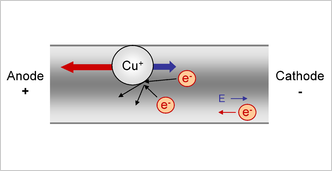
Electromigration (EM) is the transport of material caused by the gradual movement of the ions in a conductor, due to the momentum transfer between conducting electrons and diffusing metal atoms (Figure 1). The EM effect is important in applications where high direct current densities are used, such as in microelectronics and related structures. As the structure size in electronics such as integrated circuits (ICs) decreases, the practical significance of the EM effect increases, decreasing the reliability of those ICs.
Figure 1: EM is caused by the momentum transfer from electrons moving in a wire. (source: Wikipedia)
EM can cause the eventual loss of connections, or failure of an entire circuit. Since reliability is critically important for applications such as space travel, military systems, anti-lock braking systems, and medical equipment and implanted devices, and is a significant consumer demand in personal systems such as home computers, entertainment systems, mobile phones, and the like, the reliability of ICs is a major focus of research efforts in the semiconductor industry.
Reliability risk goes beyond that of physical device reliability (a challenge unto itself), extending to interconnects and their susceptibility to EM effects. Failure analysis techniques can identify failure types, locations, and conditions, based on empirical data, and use that data to refine IC design rules.
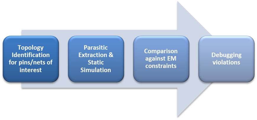
Let’s look at one approach using the Calibre® PERC™ reliability solution. The Calibre PERC tool can perform topology identification for pins/nets of interest, run parasitic extraction and static simulation, compare the results against EM constraints, then present violations for debugging using the Calibre RVE™ results viewing environment (Figure 2).
Figure 2: Automated EM analysis flow.
With basic EM analysis explained, let’s discuss in greater detail some selected EM analysis techniques, such as current density analysis, Blech Effect analysis, and hydrostatic stress analysis. Current density analysis seeks to identify the maximum current any piece of metallization can sustain before failing. Current densities below this threshold can be used to predict EM effects over time. Blech Length is a process- and layer-defined wire length at which EM effects are unlikely to occur. By finding these short wires, designers can quickly eliminate error results representing false violations. Hydrostatic stress analysis derives the degradation of the electrical resistance of interconnect segments from the solution of a kinetics equation describing the time evolution of stress in the interconnect segment.
A toolset that can combine geometrical and electrical data, like the Calibre PERC™ logic-driven-layout framework, can dynamically and programmatically target reliability checks to specific design features and elements. This flexibility allows designers to selectively target and dynamically configure EM analysis to those specific interconnect wires that are most critical, or most susceptible to EM failure. This design-context-aware interconnect reliability technology provides a scalable, full-chip EM analysis and verification solution that considers interconnect resistance, the Blech Effect, and nodal hydrostatic stress analysis for failure prediction. It also allows designers to apply EM analysis techniques to a broad range of designs and process technologies, with only minor adjustments to the setup and configuration.
Although fixed constraints work well in most IC verification cases, EM analysis and verification requires a much more flexible constraint mechanism. In current density analysis, allowing current density constraints to be a function of properties of the parasitic resistor (such as the length and width of the resistor) enables layouts to contain resistors with a smaller length and width and a higher current density. The dynamic constraint infrastructure allows adjustments to the current density constraint based on the parasitic resistor properties.
In Blech Effect analysis, the Calibre PERC solution provides access to the measured EM length for any interconnect tree. If the longest path of the interconnect tree is less than the Blech Length, the tool returns a current density constraint of some very large value, which acts as a constraint waiver for this resistor with a segment on an immortal interconnect tree.
Hydrostatic stress analysis must be performed on each interconnect tree. For each node, the Calibre PERC tool compares σi to σcrit. For any interconnect tree where σi ≥ σcrit , the interconnect tree and its individual nodes can then be highlighted in a layout viewer, as well as possible EM failure locations. The determination of σcrit is a function of process technology and segment geometry, and ideally should be provided by the foundry.
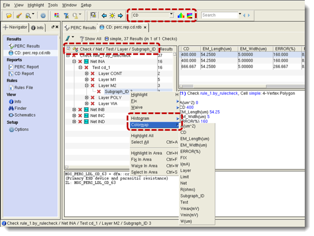
Once the EM analysis is complete, an importantaspect of ensuring reliability is debugging any errors or issues. Figure 3 demonstrates the debugging of EM violations by grouping and sorting them, then using colormaps to see current density violations/severity on the layout.
Figure 3: Debugging EM violations
Combining hydrostatic stress analysis with Blech Effect and current density analysis provides a well-rounded platform for the prediction of EM failure, allowing designers to filter out trees that are considered immortal. With the knowledge gained from such analyses, design rules can be modified to eliminate or minimize EM conditions in future designs. Using a reliability analysis tool like the Calibre PERC solution, designers can be more confident that their layouts are resistant to the long-term effects of EM, and will perform as designed for the intended lifetime of the product.
Author
Dina Medhat is a technical lead for Calibre Design Solutions at Mentor Graphics. She has been with Mentor Graphics for ten years in various product and technical marketing roles. She holds a BS and an MS from Ain Shames University in Cairo, Egypt.
Liked this article? Then try this –
This article was originally published on www.semimd.com

