Now You See Them…Now You Don’t: Recognizing DP Errors at Advanced Nodes
By David Abercrombie and Alex Pearson – Mentor, A Siemens Business
At advanced nodes, designers need enhanced error visualization and debugging to help them identify and debug complex DP errors. Intelligent error filtering and partitioning enables designers to quickly and accurately focus on and fix the root cause.
Have you ever made a short-term fix for a problem that turned into a semi-permanent solution? Maybe you stuck a bit of cardboard under a table leg to keep it from rocking, or taped a broken tool handle together until you had time to glue the pieces back together. Double patterning (DP) was a short-term fix, introduced at 20 nm just until extreme ultraviolet lithography (EUV) was ready. Now we’re down to 7 nm, and we’ve introduced triple (TP) and quadruple (QP) multi-patterning, as well as other multi-patterning variants like sidewall-assisted double patterning (SADP). Even if EUV finally makes it into the manufacturing process, we may still need to multi-pattern EUV layers!
What that means to the designer is that more and more polygons are interacting in more complex ways within the same optical radius of influence. As DP layers become more complex, in an attempt to fill the gap left by the lack of EUV and avoid TP design, the rules become more complex as well. Where before DP rules typically involved placing neighboring shapes on different masks, constraints can now stretch to 2nd or 3rd neighbors. Where increasing the distance between shapes on the same mask used to be sufficient, some pitches may now be disallowed, or required to take on the same color.
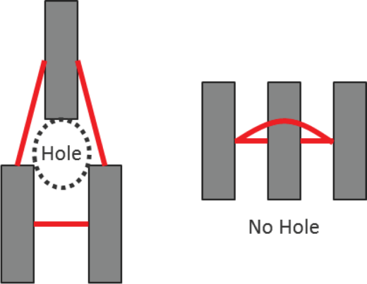
These new constraints have a significant impact on DP error detection and visualization. Designers who had become accustomed to using a physical view of the data to evaluate DP errors through the use of such markers as odd cycles can no longer rely on that approach. Opposite-mask separators can now extend across the first-neighbor to the second-neighbor shape, meaning you can have an odd cycle of separator constraints based on three polygons in a row. Because there is no visual “hole” in the middle of this odd cycle, real DP errors can be missed.
Likewise, forbidden pitch constraints mean that separators can now physically cross over polygons that aren’t involved in the DP constraint. However, a designer looking at this kind of configuration won’t readily be able to recognize that situation.
In technical terms, DP errors are no longer purely planar. A new and more precise error detection methodology is required. Cycles must be analyzed in their virtual graph representation, and validity must now be based on color parity, rather than node count. The good news is that the Calibre® Multi-Patterning toolset added new features to enable both quick understanding and resolution of these errors. Enhanced error displays provide designers with a reasonable understanding of what is actually going on, and helps them assess practical alternatives for correction. And we didn’t stop there—we also implemented new features that can intelligently filter complex errors to help designers get to root causes more quickly and identify optimum solutions more effectively.
To get the full story about these advanced node multi-patterning challenges, and how the Calibre Multi-Patterning technology helps solve them, download our white paper, Double Patterning Error Visualization for Advanced Nodes. And while you’re at it, go glue that tool handle together…
