Fundamentals of SI (Part 1) – Critical nets
To begin this series on fundamentals of signal integrity, lets start at the very beginning. Before you start doing any type of simulation or analysis, what do you have to do first, what information do you have to know? Your design probably has thousands of nets, are you going to simulate all of them?? Probably not, there’s not enough time for that and truthfully, it’s not really necessary. The first thing you have to do is determine what you care about – what are the “critical” nets in the design and what do you use to identify them?
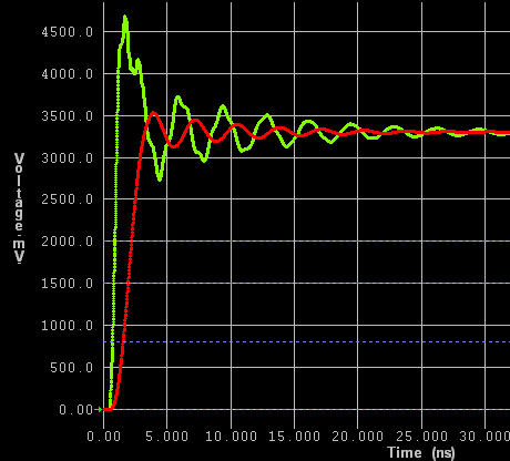
At first glance, that may seem easy. I hear answers like “clock nets,” “high frequency nets,” “all the nets are critical,” “nets faster than 100Mhz,” – the list goes on and on. While these answers do have some merit, there is one defining characteristic of a net on a digital printed circuit board that you have to think about, and that’s edge rate vs trace length.
 When you boil everything down and try to make a decision of which nets could cause you problems from an SI or EMI perspective, you want to look at the speed of the switching signal to determine if you care about that net first. As today’s silicon processes scale deeper into the sub-micron space, the edge rates of signals become faster because of the physics of the device. That ultimately means that you’ve got more potential problem nets than you may have initially thought on your design.
So we’ve got some criteria for identifying a critical net, where do we find out this information to make the judgment call on what to analyze? The datasheet is the quickest place to check the characteristics of your device pins. You can find the voltage swing, the slew rate / switching time, input impedance, and a wealth of other information in these documents. But then you have to take that switching data and compare it to the trace lengths to find out if it’s really a problem. Sounds complicated and possibly tedious (and if you had to do it by hand, it would be). That’s where you need to solicit the help of a tool.
HyperLynx SI allows you to create simple models of your devices based on the datasheets and simulate nets to determine if there are problems based on those device characteristics and the traces. This is a first step, but an even more accurate step would be to use IBIS models. IBIS models are great source to find out the switching characteristics of your device. These are industry standard signal integrity models that most IC companies have available for designers so that you can successfully use their device in your design. The HyperLynx SI product can use this information to help you determine which nets to look at as well. It reads the IBIS information from the models, it can report the length and copper delay of your nets, which allows you can quickly determine which nets you want to simulate.
If you were to do it by hand, this would take too much of your valuable time and be of minimal value, but with a quick scan from the results in HyperLynx, you can know exactly where to look without a huge time investment.
So this is the very first step, identifying your nets. You can do this very early on before routing has even started and you’re doing your initial floorplanning or you can do this in a verification phase after routing is done. It’s always best to start early though because that’s going to give you the most benefit in the end, but the choice is yours.
In the next post, I’ll talk about transmission lines. This is the other half of the critical net equation, but it’s too extensive to talk about in this post. We’ll get into some math and physics in the next post, so dust off your calculators!


