To Autoroute or not to Autoroute: Part 3
This is the final post in a routing series.
After introducing sketch routing in the first of this series, I then discussed the functionality and use models in more detail in the second post. As I wrap up this series, I will focus on the ease of use and productivity gains that you should expect to experience when using sketch routing.
Sketch routing is extremely easy to use and FAST! The only real setup required is to decide which via patterns to use and whether to route in a packed or unpacked mode (discussed last time).
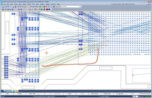
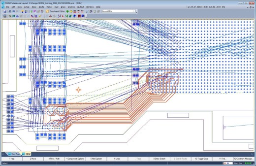
Then, just select your netlines, draw a sketch path to guide the routing in your desired direction, and then hey, presto!
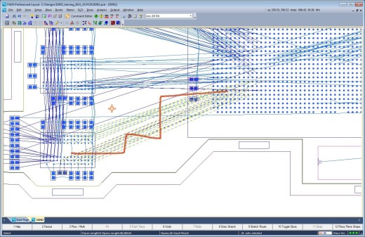
If you don’t like the results, just use the “Undo” command, draw another sketch path and try again:
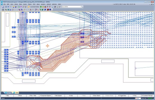
It’s not uncommon to experience anywhere between 10X – 40X improvement in productivity using sketch routing during the layout of your PCB design.
But the easiest way to effectively demonstrate how easy and fast sketch routing can really be is to just take a look at this short video (under two minutes). I’ve left the commands highlighted in the video so that you can see exactly how simple this is to operate.
Notice how quick and easy it is to route multiple sections of the BGA, even using “Undo” to use a different sketch path and changing layers for different areas. I toggled between the top and bottom routing layers by using the arrow keys, but other that, I only used four different commands:
- Select netlines
- F8: Draw sketch path
- F9: Sketch Route
- CTRL + Z: Undo
How easy is that?
In my recent article, “The Changing Face of the Hardware Design Engineer,” I mentioned that ease-of-use and reduced learning curve are key requirements that effectively increase productivity for the independent hardware engineer. Sketch routing delivers unsurpassed performance and productivity gains even for the casual or novice user.
Sketch routing is a revolutionary new concept in PCB routing. It combines the speed and efficiency of auto-routing with the manual precision and quality of manual routing. Unparalleled productivity is achieved while at the same time producing high quality results that you would believe were routed manually by a seasoned PCB layout designer with many years of layout experience.
The time has arrived to rethink the prejudices you have against autorouting and any biases you may have towards manual routing. You now have the best of both worlds at your fingertips with sketch routing.
Here’s a question I posed last time – do you use auto-routers or do you route your designs manually? What do you believe are the pros and cons of auto-routing? Let me know, I’d like to hear from you.
To learn more, download your copy of “A Stroke of Genius: Saving Time and Effort with Sketch Routing,” a routing white paper, today.
Comments
Leave a Reply
You must be logged in to post a comment.

Steve – thanks for the series on sketch routing. It’s interesting enough that I will give it a try. However, the big issue for me (and probably a lot of others) is PADS lack of area or component rules. Most of my designs require a smaller trace/space within the BGA and then neck up once outside the BGA perimeter. Esp. true for controlled impedance diff pairs.
John,
Various PADS configurations certainly support Component Rules which provide the capability to define the trace rules.
While I agree that it is not exactly the same thing as a Rule Area it does allow for different trace rules within the components outlines.
PADS Professional however does support Rule Areas. I don’t know what version/configuration of PADS you are currently using, but you may consider taking a look at the latest configurations on PADS.com (PADS Standard, Standard Plus and PADS Professional) to determine if makes sense for you to take advantage of some of the current upgrade promotions that are currently in place?
Thanks for the feedback.
Regards,
Steve