Increase the Reliability of Your Next Design
If someone were to ask you what the acronym DfM stood for, you would most likely quickly respond with a lengthy dissertation on Design for Manufacturability that would probably rival the information contained on the Wikipedia DfM page. After all, Design for Manufacturability has been ingrained into the PCB product development process for years as a way to ensure manufacturability upfront during the design phase, thereby reducing actual manufacturing costs. But how about if someone were to ask you what the acronym DfR stood for? Unfortunately, many of you would most likely pause and then try to think of all PCB related terms that start with the letter R; Rework? Returns? Real-life? When you find out that the R stands for Reliability your first response would most likely be “all of the products that I design are reliable!” But how do you quantify reliability, and how do you verify that your PCB is in fact “reliable?”
Designing for reliability is certainly not a new concept; however, it has begun to receive greater attention in recent years. The days of depending on a product’s “made in” label as an indicator of reliability are long gone. Customers have come to expect reliability across the industry spectrum, no matter where actual production occurs. As such, in order to ensure competitiveness in the marketplace, you and your design team need to maximize product reliability. One of the best ways to do so is to simulate the key reliability tests of vibration and acceleration upfront during the design phase.
Vibration analysis
Deriving the physical constraints and fatigue issues for a design prior to manufacturing is essential to reducing board failure and thereby improving product quality. In harsh environments, fatigue can be responsible for up to 20% of failures. Physical stress testing, also known as Highly Accelerated Lifecycle Testing, or HALT, reduces field failures; but is expensive, time-consuming, and can yield varying results. As a result, many design teams choose to forego physical HALT and instead rely on mechanical simulation. However that also has its own set of limitations. Mechanical simulation typically requires a specialist along with extensive library and model development, and since it generally utilizes a generic board model, the results can many times be unintuitive.
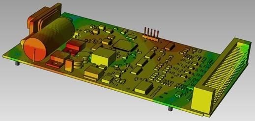
A better methodology is to bring virtual simulation of vibration and acceleration to the layout designer’s desktop in order to directly view the harmonic frequency and applied stress on all components that could potentially result in a failure. To be clear, this does not eliminate the need for physical HALT; but by eliminating early failures through simulation in layout, design teams can reduce HALT expenses and ensure that reliability specialists have more time to focus on hidden issues. Virtual simulation during PCB layout reduces design iterations and results in a less expensive product in a shorter period of time. It also allows all designs to be simulated, as opposed to just high risk designs.
Think of any recent product field failure that has been in the news. The warranty claims, loss of business and potential loss of market share can devastate even the largest of corporations. It’s a given that the marketplace rewards products that are known to be reliable, as compared to their non-reliable counterparts. High reliability provides a true competitive advantage. So why not increase the reliability of your next design by incorporating DfR simulation into your design process?


