The Necessity and Benefits of MCAD Collaboration – Part 2
In the second of this two-part blog series, we’ll talk about 3D placement and automated design rule checking. To read part one, click here.
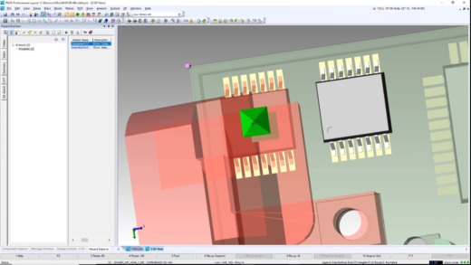
One of the biggest advantages of ECAD/MCAD collaboration is doing PCB placement in the 3D space. Rather than relying on the use of visual inspection, the tool can flag any component placement violations. This is accomplished by creating a set of three dimensional DRCs. These rules are created using the clearance icon on the 3D toolbar. These rules flag any violations that cause placement violations, in the 3D space, between components.
In PADS Professional, it’s possible to work concurrently in the 2D and 3D spaces. It can be difficult to place some components in the 3D environment (electrical components that are placed under heat sinks, or other mechanical structures, for example). Being able to place these parts in the 2D space while simultaneously viewing the results, including any DRC violations, in the 3D space is one of the very powerful capabilities of PADS Professional.
A Dynamic 3D DRC Violation in PADS Professional
Once all components have been placed, a batch 3D analysis is performed to check for any violations in the design. Using the hazard explorer in PADS Professional, those violations can quickly be identified and corrected. Once the violations have been fixed, a design proposal can be exported to the collaboration folder. This is not a complete design file. It only contains the changes to the original file supplied by the mechanical engineer. Using the preview capability, the mechanical engineer can quickly review and accept, or reject, and propose changes. If any changes are rejected, a note can be attached and the file sent back to the PCB design engineer for further changes.
Likewise, if the mechanical engineer makes any changes to their design, they can export a proposal to the collaboration folder and alert the electrical engineer of a pending change. The PCB design engineer can open the file and using the show physical change feature quickly see any changes made by the mechanical engineer. Once all proposals have been reviewed and accepted by both the PCB designer and mechanical engineers, the design can proceed to fabrication and assembly.
Because both NX and PADS Professional support the IDX interchange format, it has been used in this example. Not all MCAD tools support the use of the IDX format. In such cases, PADS Professional also supports other outputs formats, such as STEP, IGES, SAT and PDF file formats. For MCAD tools that do not support the IDX or IDF formats, STEP is the best option for generating a realistic looking board model for visual inspection. The resulting STEP file is not an assembly, but one large solid model. So, changes cannot be made directly to the STEP file, but it can be used for visual inspection and documentation purposes. PADS Professional also supports the importation of STEP files for the creation of board outlines and mounting holes.
For companies that do not have an MCAD tool, PADS Professional can export files in the PDF format. This is the easiest way to share data with anyone who does not have access to an MCAD tool and works quite well for viewing 3D data, including the ability to rotate an object within its 3D space. The use of PDF export from PADS Professional is an easy and convenient tool for generating product documentation and for sharing data with stake holders.
Although these other formats are useful for those without an MCAD tool that supports the IDX format, the use of intelligent data allows an advanced MCAD tool like NX to provide advanced capabilities such as thermal analysis.
Using the filtering capability of the MCAD collaboration dialogue within PADS Professional, the PCB design engineer can select which data is exported to the mechanical engineer. The mechanical engineer will import this data by selecting the import ECAD icon from the PCB exchange toolbar within NX. Once the electrical data has been imported the simulation environment can be set up from the PCB exchange toolbar. The mechanical designer can then go directly to SIM center and begin the thermal analysis of the design.
Conclusion: The Benefits of ECAD/MCAD Collaboration
Collaboration between design disciplines is now mandatory to meet today’s tight product design schedules. Visualizing and using the design content created by others within the product design team allows faster design times and provides the ability to make better decisions. Changing a design philosophy can be a challenge, however continuing to use obsolete tools and methods allows competitors to be first to market.
Reasons to choose PADS Professional include:
- Use the ECAD/MCAD collaboration available in PADS Professional to reduce design time
- Use 3D placement to eliminate costly design spins and mistakes
- Produce a higher quality product
- Explore new ideas resulting in a better product with more advanced features and capabilities
PADS Professional offers powerful, easy to use ECAD/MCAD collaboration features that allow electrical and mechanical engineering team to work together in a more efficient manner that results in getting better products to market faster. Engineers can seamlessly share data while working within their familiar tool environments. Costly design spins are eliminated by catching issues that slip past less efficient, traditional methods. Today’s complex products are no longer just a PCB. They are complex electro-mechanical systems consisting of multiple PCBs, thermal solutions and mechanical enclosures. PADS Professional is a modern, collaborative tool to solve these complex design challenges.


