Products
Unfolding the Future of PCB design with Rigid-Flex
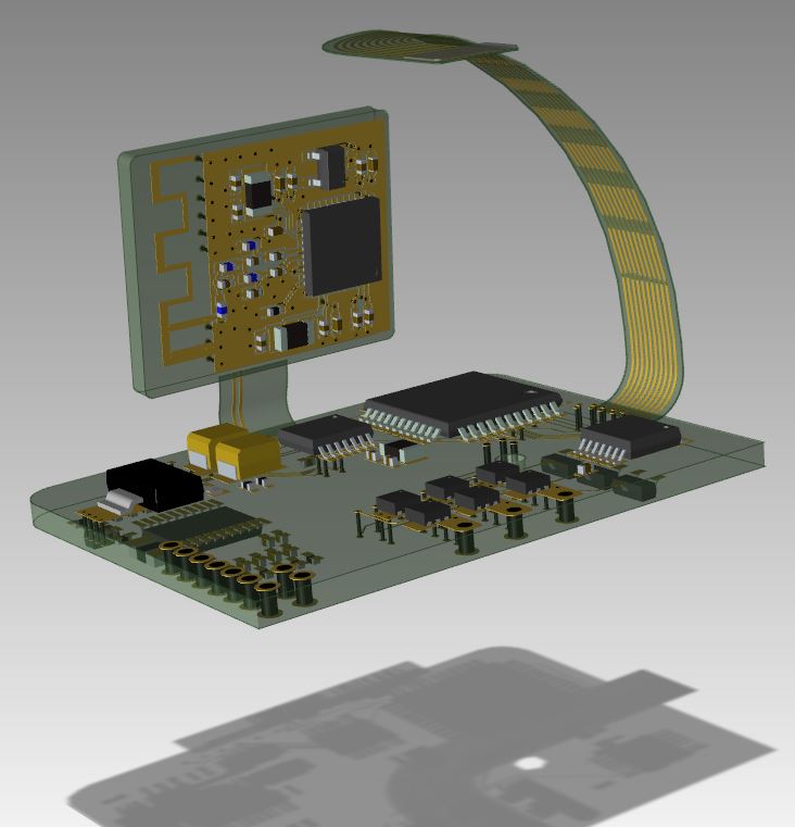 One of the most difficult aspects when creating a design that’s pure flex or rigid-flex combination is that it needs to bend. Unless you’re designing your flex in a mechanical tool, which contains zero intelligence when it comes to electrical design, visualizing bending is not available in most electrical engineer tools today.
Being able to define as many bend areas as you need with finite adjustment for length and bend angle from your electrical engineering tool eliminates time consuming back and forth iterations with mechanical engineering. In addition, rules are available within the ECAD tool to ensure you don’t exceed industry standards for minimum bend radius or bends to close to the rigid end of the flex.
When folding a flex with components, visual inspection methods can lead to unseen errors. Using three dimensional DRCs assist with eliminating manual inspection errors. You’re not just limited to “Pass” or “Fail” results 2 distinct levels of rules can be created. Absolute minimum, which would result in a collision, and Margin, which flags possible collisions should tolerance stack-ups be exceeded.
Aside from 3D visualization there are several other flex circuit design capabilities that a modern electrical engineering tool should include items like, intelligence for stiffeners, flex and rigid board aware library parts, intelligent manufacturing and assembly information, and board stack-up support for multiple regions. Each of these when done manually lead to time delays in final product release due excessive prototyping and design reviews.
Let’s take a closer look at how these advanced capabilities reduce design time and produce a higher quality product.
Board Stiffener
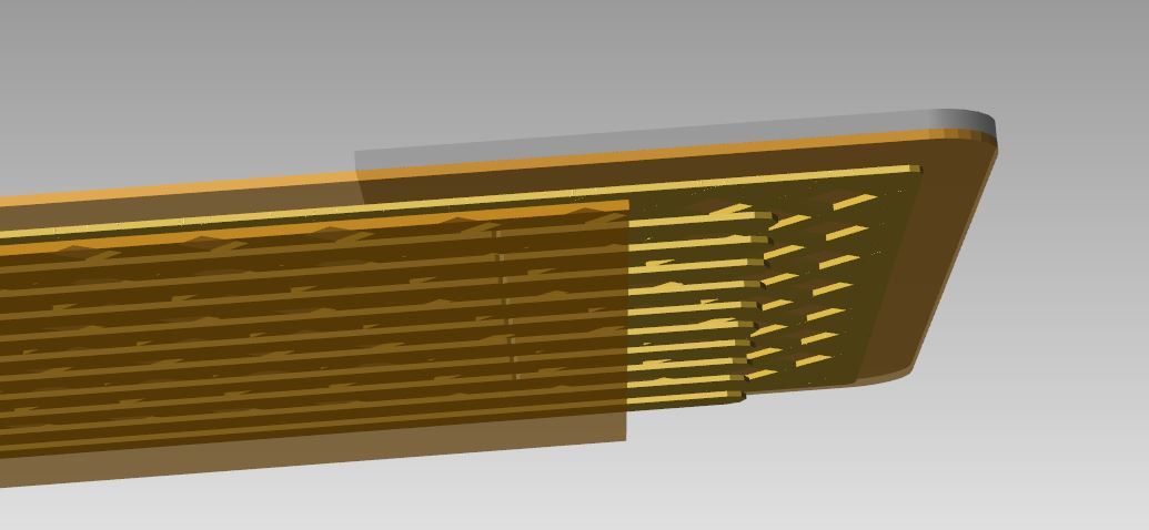 Whether you’re designing a pure flex circuit, flex cable, or rigid-flex combination there may be requirements for certain areas of the design for rigid backing. An example might be a flex cable from a rigid board that will attach to a connector on a second PCB. These types of cables use fingers, much like a PC add-in card that mates with a connector. The base material for most flex circuits is usually made from Kapton and quite thin and flimsy. As such, it’s not practical for the finger area, which connects with an external connector, to use only Kapton. To solve this problem designs add some type of thick rigid material based on the connectors requirements. To help simplify the design process additional data can be built into the footprint so no additional design content will be required which could be forgotten. In addition, being able to view the stiffener in its appropriate location in 3D adds to our ability to validate and avoid expensive and time consuming prototypes built.
Flex aware library parts
When placing components in a flex region the solder pad and opening require rounded pad shapes based on design requirements for high reliability. Most tools do not provide provisions to add multiple pad shapes for a given layer.
For this reason it is necessary that library parts create support the option to define solder and cover layer openings that are specific to flex circuits. How are these used? When the part is placed on a rigid region of a PCB it will use the standard pad shapes. When moved to a flex region, the standard pad shapes are automatically replaced with those defined for flex.
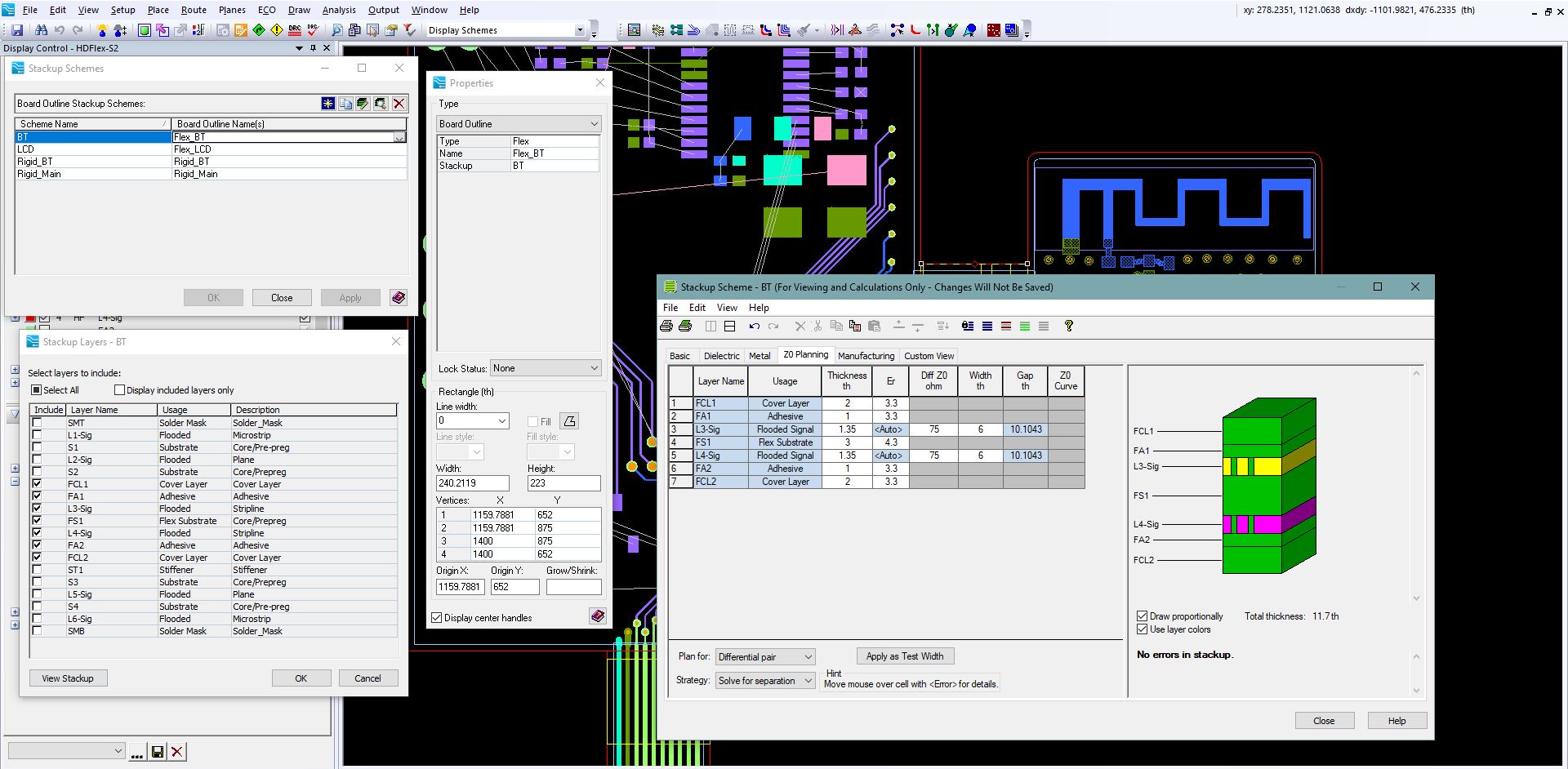
Rigid-flex stack-up regions
One of the more difficult issues to deal with for rigid-flex circuits are the various flex and rigid board stack-up regions. Being able to create an overall stack-up and then independently select the appropriate layers for a given region simplifies our job for documentation and manufacturing. Here’s an example, we have a design with 2 flex regions and 1 rigid. Flex areas of the circuit require some special layers not used in the rigid region. Those being, cover-layer for top and bottom and in this example a stiffener. Our master stack-up will contain all layers required for both rigid and flex. We can than create stack-up schemes which can be reused between regions or we can define stack-ups by region.
Intelligent Manufacturing and Assembly data
We’ve just covered how intelligent flex features are created and used to automate the design process. This should not end when it comes to outputting data to have our design manufactured. With intelligent manufacturing output like ODB++ we can circumvent many of the drawings and discrete files we need to create. This comprehensive manufacturing output should include all the special features we’ve defined during our design; stiffeners, bend areas, cover-layers, flex and rigid regions, stack-up regions, etc. In addition, reviewing the final output as a sanity check is always a good idea.
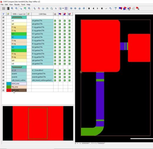
Having a free ODB++ or Gerber viewing tool allows us not worry about finding and maintaining a 3rd party product.
At the end of the day most MCAD or ECAD tools will allow you to create a design for flex or rigid-flex PCB.
However, do you and your company want to spend countless hours in design reviews and creating prototypes to ensure your design meets quality, fit, and function requirements? Your design tool needs to understand all aspects of rigid-flex design along with 3D viewing and verification. Avoiding an application like this would be like doing mechanical design with pencil, paper, and rulers again.