Holding It All Together: Welds and Fasteners in NX


In today’s world of product development there are software tools that enable design, analysis, manufacturing tool path generation, simulation and predictability. We have databases, data management and product lifecycle management tools. Nearly every area of our business is enhanced by the use of computers and software. A lot of time can be spent using these tools for their own sake, however, with little return if the goals and end game are not kept in focus. Understanding and making intelligent use of these software tools is the key to being successful. One area where I have found this to be especially true is in the definition of joining and fastening, which includes welds, rivets, nuts, bolts, glues and structural adhesives.
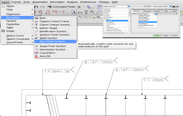
It wasn’t so long ago when information regarding joining was most typically conveyed on the face of a drawing. In the case of welds, there is an entire set of standard symbols that are used to define what size, shape and type of weld should get used. Oftentimes, nuts, bolts and fasteners are defined in tables with various parameters exposed in the cells of the tables and then placed on a drawing sheet. Glues and structural adhesives are often ‘cartooned’ in on manufacturing sheets and depicted in various different methods and styles. The primary purpose of portraying this information on the drawing is to define how the assembly should be manufactured. Though simplistic in its approach this method can be very effective in certain design situations. If the assembly is simple with obvious joint locations and standard joining methods and if the product doesn’t change very often then this method is all that may be needed. A proficient designer can annotate a drawing with weld symbols, fastener tables, notes and labels in a short amount of time.

If however, the product you are assembling is going to change often, if the weight and mass of the product is critical, if there is a desire to automate the joining definition, automate the manufacturing of the joint, a need for complex planning where joining will be divided amongst multiple work stations, then a more comprehensive joining solution is required. Understanding which of the above requirements need to be satisfied, and to what extent, will determine the software products and strategies that should be employed.
Let’s explore each of these one at a time. If you have a product that is expected to change often— either in its initial design phases or frequently after it is released—then it will be important that the joining definition and the way it is conveyed to manufacturing are in synch with the product design and easily adaptable. In this case, a joint definition that is separate from the drawing symbol or fastener table values but still associative to them is a good idea. This separate joining object should be easily updated to accommodate the design change and then be able to reflect this change in its definition (weld symbol) to manufacturing. In the case of a joint defined by NX, this is accomplished by use of an NX joining feature. This feature’s placement is driven by parent geometry and the definition exposure to manufacturing, whether via a symbol on a drawing or PMI is driven from the joining feature itself, thus everything stays in synch upon editing.
If understanding the joints’ weight and mass properties are critical to the overall product design, then it may be important to have the joints modeled as solid bodies in the product assembly. Though there are a number of various methods that can be used for calculating weight of an assembly, a very simple method is to have all of the product components and joints modeled in CAD. NX and the Weld Assistant product provide solid based modeling of nut and bolt fasteners, arc welds, discreet fasteners, structural adhesives and sealers. This makes it a trivial task to tally up the weight and analyze the mass properties of the assembly, providing very good estimates of these properties. Another benefit of having the arc welds and sealers modeled as solid bodies is that they can be made available to CAE analysis software tools in a format that is recognizable.
Automation of a joint’s definition is very important in some industries including aerospace and shipbuilding where joining strictly adheres to a defined specification. For example, an arc weld on a ship is determined by where on the ship it occurs (is it on the top deck or in the room containing the nuclear reactor?), what types of metal are being joined, and the thickness of those plates. A rivet’s definition in an aircraft is determined by the stackup of panels that is joining. As you may well imagine, there are tens of thousands of joints defined on ships and airplanes, and it would be extremely tedious and error-prone if each definition was left up to a designer’s determination. In this case, a software tool that allows customer-specific rules (that matched those in the specification being worked to) is required. NX has various tools that do this including the Rules based weld application.
Still another desire may be to utilize some type of robot or programmable machinery to create the joint. It could be a spot weld, arc weld, or sealer applicant. In this case, it is important that the definition of the joint can be passed to the controller or robot programming software in a form that can be utilized. Along with the joint definition, the coordinate values of a discreet weld and the center line path of the arc or sealer beads are important. This information must be exported out of the CAD system and transferred to the destined manufacturing system. The NX joint definition can be exported into either a comma separated value (CSV) file or an XML formatted file.

In the manufacturing of many large and complex structures—such as automobiles, ships, airplanes, locomotives and heavy machinery—the manufacturing build process happens at different work stations in a very well-defined and sequenced set of process steps. The processing of the joints is critical to the overall manufacturing process. It is important to identify what joints will get applied in a specific station. This enables weld robot paths to be developed, determines what manufacturing resource is required (a welder with the proper certification, for example) and indicates the physical number of joints or length of weld required at a given station. A variety of factors can complicate this processing. For example, in the automotive industry a common vehicle may be built in different locations around the globe and each location may have different assembly equipment thus requiring a different manufacturing plan of the same joints. This alone requires that each joint is a separate object that can be accounted for in any build plan. In the ship building industry, it is not uncommon for a weld’s strength efficiency to be defined by engineering, but the weld’s physical cross-sectional shape to be determined by the manufacturing plan depending upon the orientation of the plates to be welded at a given work station. Thus, a joint object must be flexible and able to carry both a design and manufacturing definition. If the requirement is to define joints that need to participate in this level of processing, then the joining solution will need to comprehend the difference between engineering and manufacturing definitions and be available in the proper format in the database so that process planning and simulation software solutions can make use of them. The Siemens PLM Software suite of tools including NX, Teamcenter and Tecnomatix have the capability and interoperability to be able to support such complex joining lifecycles.
In summary, each customer’s joining needs are different and there is no one solution that will work for everyone, but by understanding the joining requirements, a customer can make use of current software applications to deliver the proper solution while saving a lot of time and effort otherwise wasted!


