Enhance electronics and mechanical design with NX Flexible Printed Circuit Design
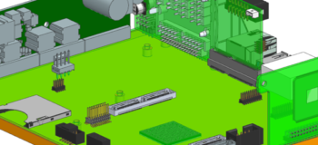
Following the updates from last months NX release, we want to be able to bring you more details surrounding the different applications within NX. This post focuses on NX’s Printed Circuit Boards application. Please see below for more details.
Overall in this release, Flexible Printed Circuit Design enhancements focus on electronics and mechanical design collaboration in a managed environment, and productivity workflows for rigid-flex and flex boards. We will be looking into the following updates:
•Conversion of rigid-flex designs into Flexible Printed Circuit Design (FPCD) native parts
•Improved error handling and user feedback during conversion
•Enhanced electronic component placement workflows
•Support managed IDX collaboration within Teamcenter co-design object
There is a video demonstrating all of this at the end of this article.
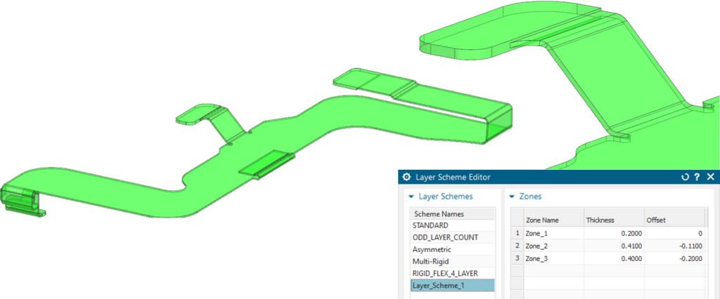
Conversion of rigid-flex designs
With the conversion of rigid-flex designs you will find that there is a simple single click to do just that.
What’s new?
•Consistent to existing functionality
•Automatically generated layer scheme
•Reuse of created layer schemes

Improved error handling and user feedback during conversion
Improved error handling and user feedback during conversion supports conversion of a common set of problems in model geometry.
What’s new?
•Better handling of tolerance issues, non-concentric bends, split bends, non-parallel faces, and non tangent bends.
•Improved messaging with localized highlighting
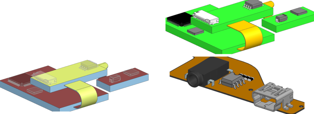
Enhanced electronic component placement workflows
What’s new?
•Associate Object for assembly components
•Layer settings for flat solid
•Component cross selection and highlighting
•Visual reporting for top/bottom face identification
•Pin 1 and CCP identification on flat solid
Thank you for taking a look at the recent NX PCB enhancements in this latest release of NX. Follow our blog for more updates in other areas in the coming weeks
