Tilt Tool Axis

I showed in a previous blog post how to use Divide By Holder to keep the cutting tool as short as possible. Today I want to show how to take advantage of multi-axis capability of NX CAM and CAM Express to keep the cutting tool as short as possible.
Derek Hart wrote an excellent blog post on some of the new functionality of NX9. One of the items mentioned was Tilt Tool Axis. This functionality was originally introduced in 8.5 and has been enhanced in this version.
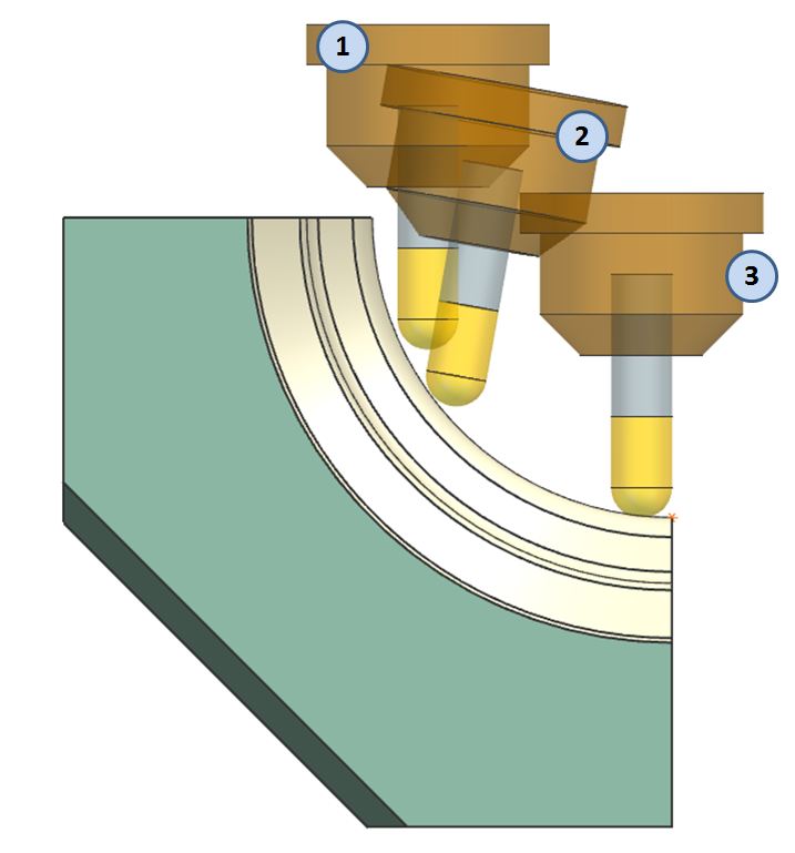
Tilt Tool Axis allows the user to select any 3-axis tool path and convert it to a 5-axis tool path ONLY WHERE NEEDED to avoid tool holder collisions. This is especially useful for machining nearly-vertical surfaces that are frequently found in molds and dies. Consider the picture below; Position 1 indicates the tool at the beginning of the cut, Position 2 indicates the tool midway through the cut (where the axis is tilted as required), and Position 3 shows the tool at the end of the cut (and the tool axis is returned to the original state).

The following video helps to explain how the tilt tool axis option is used.
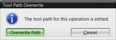
Remember, Tilt Tool Axis is an activity done AFTER the operation is generated. If you return to the operation and generate it again, you will lose the tilting effect. This warning is therefore displayed:

If you look in the Operation Navigator, the “wrench” symbol also indicates the path is edited.

Thanks for reading. If you have questions or an idea for future posts, let me know in the comments section.
Jim has a Master’s degree in Business Administration from the University of Central Missouri. He has over 30 years of experience in the manufacturing industry, and over 25 years of experience in the CAD/CAM field. He serves as Field Support for Siemens PLM CAM products. Prior to his current role, he held stints as CNC Programmer, CAD/CAM Department Manager, CAD/CAM instructor, and Project Coordinator for Siemens PLM CAM software development. He is a founding member of the Speling -n- Grammar Association.


