Creating a CPU thermal model from scratch quickly
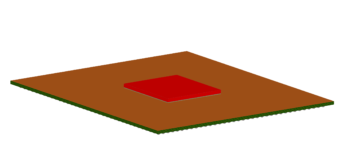
CPU created in Simcenter Flotherm Package Creator
The most important component within a typical PC computer is the CPU. So when it comes to creating a CFD model of a computer, correctly modelling the CPU is priority number one.
You could just take the easy route and create a block of the same size and material and throw it into your model and solve. Which is exactly what I did to start.
I had the dimensions of the CPU and created a simple component in EDA Bridge within Simcenter Flotherm XT. A power was added and the material was set to silicon as that was the material of the die. Surely this will give results close enough while keeping mesh count down?
It will to some extent. However, a CPU is not only made of silicon. There is the substrate, solder and many more materials, which all have different thermal properties meaning the heat spreading within and heat transfer through the component and board will be different between a single block and a real CPU.
So how do you create a CPU package thermal model?
With the newly-released Simcenter Flotherm Package Creator engineers can quickly generate clean CAD geometry based, detailed chip package models. This helped me create a very accurate model of a CPU in a matter of minutes. It would otherwise have days of effort to create in a CAD program. The only thing I needed was some dimensions about the Intel i5 chip I was modelling.
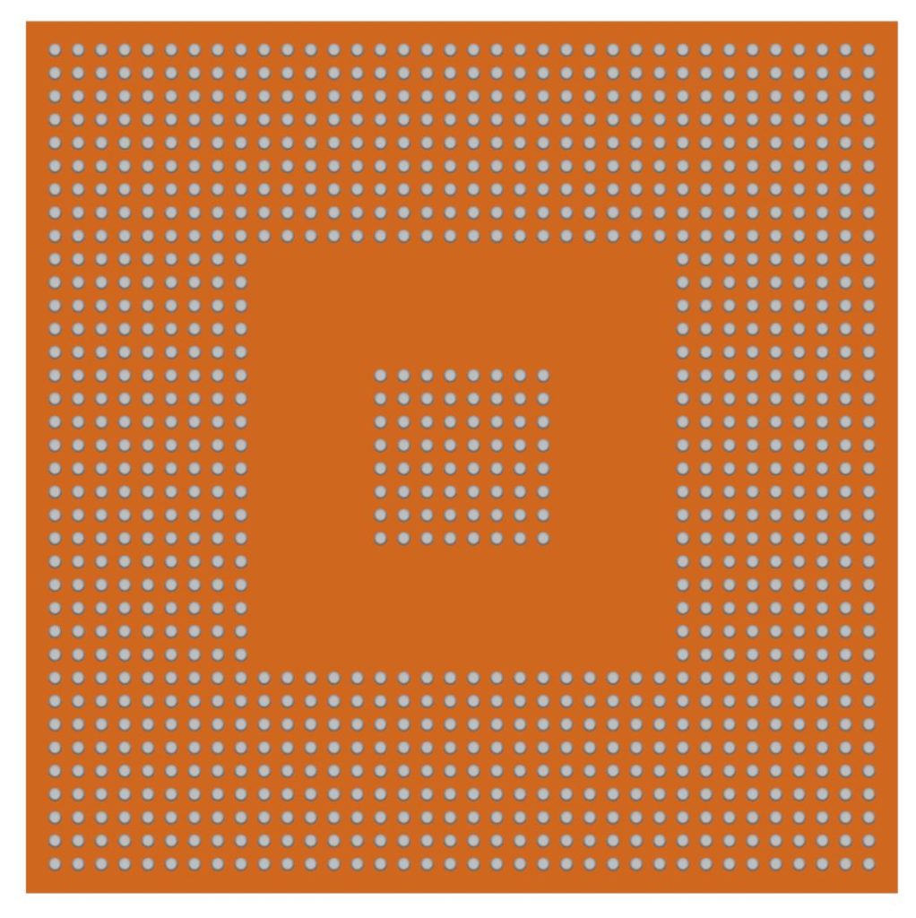
While this was detailed, it created its own problem. The solder balls were so small that it caused the mesh count to be over 1 million! To avoid overly long solve times at this early stage of design evaluation, I decided to model the solder as a compact model which is still quite accurate as it uses an orthotropic conductivity for the solder ball region. This reduced the mesh count to less than 200,000 and saved me over an hour in solve time.

It was easy to export the package and use EDA Bridge to replace the simple component and create some interesting results on a motherboard. These were close to the results seen in the previous blog post.
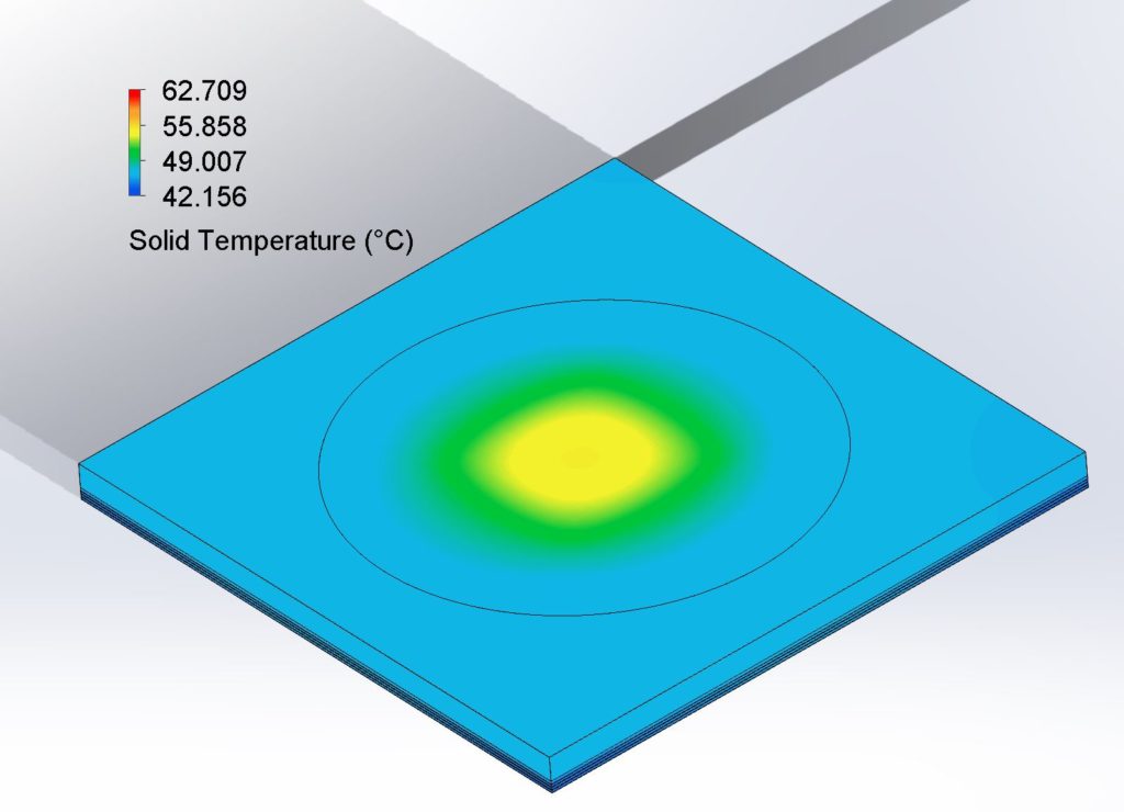
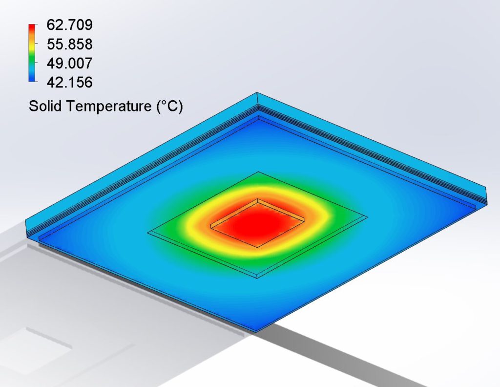
Temperature results for the top (left) and bottom (right) of the CPU
Incorporating the CPU thermal model into a 3D system CFD model
And here it is. The updated board with the improved CPU underneath the heatsink and fan set up.
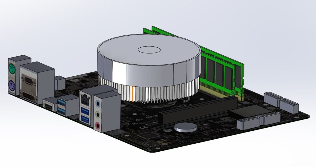
This is one step closer to creating the complex model required to determine the best cooling solution for this computer system.
If you would like to know more about Simcenter Flotherm XT, and try it out for yourself, you can with a free cloud evaluation.

Comments
Comments are closed.