A CFD Story: The Brief History of Formula One Aerodynamics

If you are a casual fan of Formula One it’s likely you may have come across either the phrase “CFD” or “Virtual Wind Tunnel Simulation” in any TV commentary when the subject of aerodynamic design comes up. So in order to address this I thought it’d be fun to take a series of cars over the first 50 years of the sport to tell the story of what’s going on with the airflow around them. So I took it upon myself – with access to Simcenter STAR-CCM+ and NX – to draw and analyze 11 of the biggest cars to grace a racetrack up to the late 1990’s, before things got too complicated.
CFD: The Basics
Computational Fluid Dynamics (CFD) is a program that any engineer who is designing anything that interacts with a gas, a fluid, a solid (or multiple combinations of all three) where at the very least there is some kind of “flow” problem that simple hand calculations won’t cut it. It does this by taking a 3D representation of the object (drawn in a CAD package) and surrounds it with millions of little connected blocks (a mesh) which talk to each other to solve very complicated equations (the Navier-Stokes equations) which describe how fluid flows from a mathematical point of view. It’s what engineers use to solve the hardest problems out there designing ships, rockets, engines, turbines, nuclear reactors and the list could go on..
Under Pressure
To look at a racecar with wings for the first time, its easy to think that the angle of the wings must push or deflect the airflow up, a bit like a flat plate would, and push the car into the ground. In actual fact, racecars use the underside – the gap to the racetrack – to create suction that pulls the car to the ground to a greater extent than the upper surfaces may push the car to the ground.
So lets have a look at some of the first batch of cars in the following movie:
This shows pressure Red = high, blue = low. It is clear that the wheels have lots of red at the front (so generate a lot of drag) and a lot of blue on the top (so they actually generate lift). The early cars were quite streamlined, so the pressure is mostly even over the car until you get to the back where the pressure is low, this is due to the flow starting to become “dirty” (known as flow separation) at the very rear. The car that starts to use wings shows that while there is some high pressure on the top side, its the deep blue on the underside that is generating the grip.
As we progress into the next decade, the wings get bigger and lower – but due to the wheels or the engine cover they might not work very well, then towards the end of the 70’s the next step forward came – ground effects. This was taking the fact that the underside of the wings worked so well at creating low pressure using them over the whole underside of the car was sure to work well too, and it did when adding in skirts to seal them to the track – you can see how much more blue there is on the cars – so much so that the early 80’s saw front wings being taken off to maximise the amount of air going under the car.
As speeds in the corners went up rule changes saw the ground effect era end, the underside became flat and a small diffuser (the angle up after the rear wheels) became mandated as standard. But as aerodynamic design effort increased this was slowly clawed back until we get to the later cars with rear wings and diffusers now working together to increase down force levels.
Know your Flow
CFD is powerful to not only predict the pressure acting on a surface so that the forces generated are known in advance of building a physical prototype, it also is incredible useful to analyse the flow features to understand what is happening so that you can exploit it. For vehicles that travel well below supersonic speeds the flow starts to bend around it well in advance of the vehicle itself, so its not a simple case of thinking that air will directly hit whatever surface is infront of it. And it is by visualising the flow that coming up with the next design improvement will probably come. So we can inject tracer particles into our CFD model to look at some of the interesting flow features of the front wing flow.
We can see in the video that the early wing had no endplate or wingtip, but a vortex still formed due to the difference in pressure between upper and lower wing surface rolling the flow around the tip. It’s also clear that the underside – where the pressure is low, has a higher velocity – the two are related and this is amplified because of the short gap between the car and the ground. Subsequent designs saw endplates attached to the tips so that the pressure difference could be maintained across the whole wing. In doing so it created stronger wing tip vortices that roll up around the endplate itself. Varying cars had varying front wing widths, and you can see that some vortices actually hit the front tyre and are destroyed. Yet in the more recent cars it was discovered that this vortex is important to keep near the car as the front suspension opened up this area and “barge boards” became a key component.
So lets have a look at the effect on the floor of the car. The intial cars in the 70’s had wings but a flat floor, but once the ground effect cars added airfoil section shaped tunnels the air flow speeds massively increased below the car. However due to the rear transmission the central part of the floors were still relatively flat, skipping the rule changes banning ground effect cacrs in the 80’s, the design focus on the difuser at the rear managed to channel the flow back in towards the centerline of the car so that it could help the rear wing (and vice versa) by making packaging of the engine/transmission/rear suspension crucial to overall aerodynamic performance.
So rather than me talk through the results of the rest of the two movies, lets just watch the first batch of cars leading up to the first proper ground effect car and look at how the vorticity changes around the car and the wake behind them changes from a simple one to a very complicated, turbulent one. Also take note of how using multiple element wing sections changes.
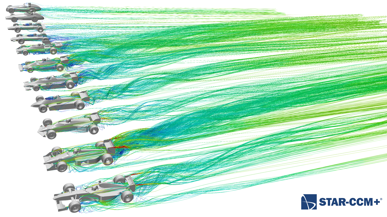
The remaining years sees the flow at the rear become dominated by strong endplate vortices as well as significant upflow from the rear wing and diffuser interaction – also increased by the presence of low positioned “beam” wings. So the flow – whilst still “turbulent” it is more organized than the chaotic flow of the late 70s.
So from this point on, the late 90’s was when the use of CFD in motorsport really exploded. It had been used on some level designing the airfoil sections themselves, but increasing CFD, computing and CAD power saw a rise in how much design refinement was done before anything hit the wind tunnel or the race track. Anyone who is a fan enough to see pictures of the cars testing with loads of probes sticking out of the cars, this is for corellating all three streams of performance data: CFD, Wind tunnel and track.
It’s funny that in the process of doing this little study, I intially thought that for cars of the 50’s and 60’s that were slightly curved and streamlined “how did they do this without CAD?” yet they are some of the more beautiful, as I got to some of the cars in the 80’s when 3D CAD use really came of age, the cars became a bit more simple as they maintained similar cross sections, particularly for the sidepods. But it wasn’t until I made the following picture where I lined the cars up with each other that really shows the story, in that the flow behind the cars has dramatically shifted from more or less tracking along the same direction to being worked very hard – become dominated by strong vortices and is deflected upwards to great extent.

So there you have it, a very brief outline of the very basics of the flow and main features of some of the fastest cars of their time in the world. I’d like to know if anyone can name all 11 cars that were the basis of those here, comment below! Are there other past cars you would have liked to see?
Comments
Comments are closed.


Hello Chris, how can I get in contact with you about your CFD pics?