Engine design study with Simcenter Amesim 17 & Simcenter STAR-CCM+

 Among the many factors which directly influence engine performance on a whole operating range, one that needs to be tackled by design engineers is the influence of the intake line geometry on air induction processes, more specifically gas transport and acoustics.
This topic is particularly difficult to tackle from a modeling point of view: although a system simulation approach is mandatory to address the multi-physical aspects of engine performance, the refined characterization of gas flow through an intake line often requires to go beyond the hypotheses that typically need to be set at a system simulation level.
Through the joint use of Simcenter Amesim 17 and Simcenter STAR-CCM+, a co-simulation approach is now proposed: the goal is to extract dynamical information from 3D CFD modeling of air flow in complex geometries directly inside a system simulation model.
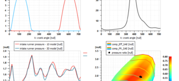
The typical use case of such an approach is the modeling of air flow through an intake line manifold using 3D CFD, as coupled to a 1D-based representation of the whole engine system. It allows users to either go beyond the typical system simulation approach for intake line modeling, which needs some calibration on charge loss and effective geometries, or to validate such approaches if they are already available in a study. This way, the fine impact of the manifold geometry on gas dynamics is better captured, and directly fed to the engine model for performance prediction.
A direct co-simulation approach between the 3D CFD and system simulation models is here required due to the highly dynamical behavior of flow through the intake line. This poses severe technical challenges in order to ensure that all information is correctly passed through the coupling interface, and that modeling hypotheses are retained. Using dedicated components from the Simcenter Amesim CFD1D library, a full engine model can be built, such as the available solution demonstrator for a turbocharged spark-ignition engine with 3D CFD co-simulation.
 Main demonstrator sketch
The modeled engine is a 2000cc size, with direct injection and variable valve timing, and includes a turbocharger. The intake manifold is modeled both in 1D and 3D CFD, through an interface with a Simcenter STAR-CCM+ manifold model also available inside the demonstrator. Both the system simulation model and the CFD interface are packaged inside a parameterizable supercomponent for ease of use. Two intake manifold models: the system simulation model on the left and the 3D CFD interface on the right
A pre-cycling strategy is necessary for such an approach for efficiency in the workflow. In that respect, the study must begin by a calibration of a system simulation model in order to reach a reasonably converged state for the system and speed up the co-simulation. The manifold part of this system simulation model can, for example, be obtained through the use of the Simcenter Amesim CAD Import tool.
Once this state is reached, actual co-simulation can take place, and convergence to the engine operating point of interest takes roughly a couple of hours. Interactive viewing of flow fields with Simcenter STAR-CCM+
The impact of geometrical features on detailed acoustics can then easily be identified, and possible modifications can be assessed.

The interest of this approach is that it can be most easily adapted to a similar study on intake line acoustics and performance, through the re-use of the provided manifold component, which includes a ready-made interface for Simcenter STAR-CCM+ co-simulation. That way, the system simulation engineer can more easily take the best of what can be provided by advanced 3D CFD tools, and thus improve the performance predictions of its engine model in Simcenter Amesim.
Want to see how it works?


