Fluid-Structure-Interaction FSI with mechanical contact? In one simulation? Yes, in one!
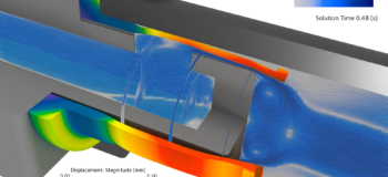
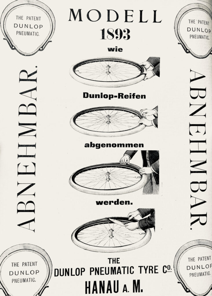
What do the safe operation of high-tech sensors and cameras of 21st-century automotive and the invention of the Dunlop bicycle valve from 1891 (US patent US455899) have in common?

Many applications such as seals, gaskets, valves, and nozzles imply Fluid-Structure Interaction (FSI) in conjunction with mechanical contact between solid bodies. Due to the highly non-linear nature of contacts, we often tend to neglect the respective contact modeling especially in multi-physics applications such as FSI. For a number of applications, being able to model mechanical contact along with fluid-structure interaction is even the key enabler, to do a physical meaningful simulation at all.
Read this article to understand how and why!
Solve challenging coupled multi-physics applications in a straightforward manner
Sensor & camera nozzle, a clever design
For cameras and sensors to produce a sharp image or signal, they require a clean lens. Since many of those installed in automotive are exposed to dirt and debris regular cleaning is a must. This is usually done with the help of a liquid spray from a nozzle.
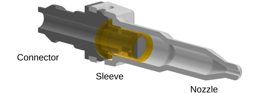
You see below a simple but clever design of a sensor and camera nozzle. It consists of just three parts: a connector, a rubber sleeve, and a nozzle.
Modeling mechanical contacts between solid and elastic bodies, introduction of a new model
The rubber sleeve seals the assembly and acts as a valve. To illustrate this, we have created a 3D model in Simcenter STAR-CCM+. The connector, as well as the nozzle, are assumed to be rigid, while the sleeve is modeled as an elastic body. The contact between -sleeve and connector- as well as -sleeve and nozzle- is included. This is possible thanks to the ability to now model mechanical contact with any tessellated geometry parts.
The animation below shows the assembly process of the three parts:
- First, we push the connector into the rubber sleeve
- Next, we squeeze the rubber sleeve between the nozzle and the connector thereby sealing the assembly.
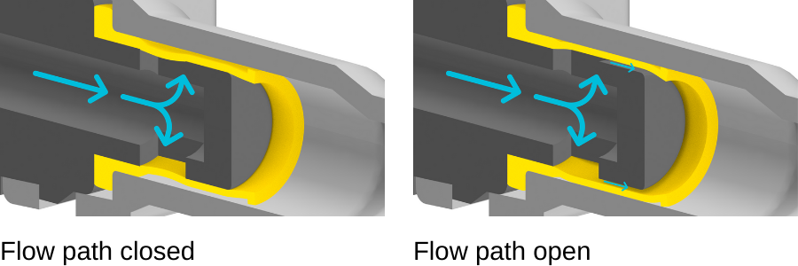
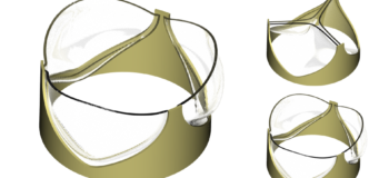
Once installed, the sleeve closes off two radial holes in the connector (see left image). As soon as the cleaning system is activated a pump is being switched on. The pump pressurizes the liquid, and the sleeve deforms because of the liquid pressure. This opens a flow path underneath the sleeve (as shown on the right).
A model inspired by Dunlop bicycle valve
The bicycle valve developed by Dunlop 1891 works exactly like that. In the image below, you can see the radial holes in the valve body covered by a thin rubber sleeve.
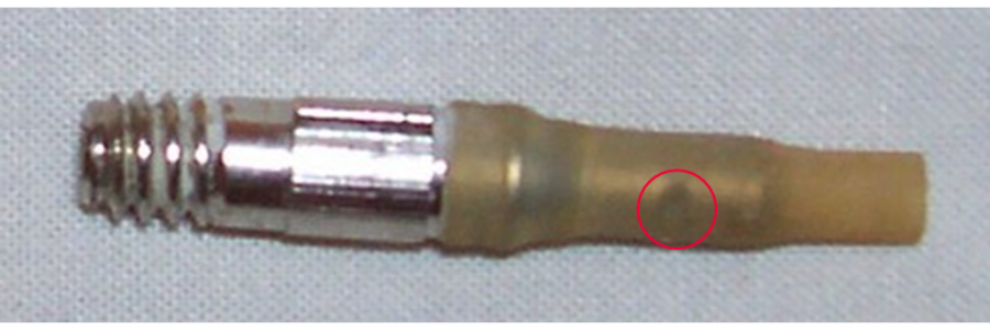
FSI simulation with mechanical contact – an application example
The pragmatic approach
The model of the sensor and camera nozzle has proven to be very useful to illustrate how the design works. But what about the engineering value? For example, how much liquid will leave the nozzle per unit time considering that the pump of the cleaning system can generate a pressure differential of 1.0 bar?
Let’s approach this question in a pragmatic manner.
- First, we apply a pressure load of 1.0 bar on the internal surface of the sleeve and compute the deformation.
- Next, we extract the flow path considering the deformed sleeve.
- In a subsequent flow simulation, we then apply a pressure differential of 1.0 bar and compute the flow field.
The video below shows the results of this approach: the average mass flow rate is about 1.93 g/s.
FSI simulation with mechanical contact
The above approach is problematic and may lead to wrong engineering decisions. Why? In reality, the deformation of the sleeve impacts the flow, while the flow impacts the deformation of the sleeve.
In order to increase the accuracy and the engineering value of the model, we must take the two-way coupling between fluid and structure into account. Since the flow model and the structure model are part of the same Simcenter STAR-CCM+ simulation this is straightforward and does not even require co-simulation.
The video below shows the results using FSI simulation with mechanical contact. The pressure at the inlet is being ramped up from 0.0 bar to 1.0 bar over a period of 1.0s, after that the pressure is kept constant at 1.0 bar. The average mass flow rate between 1.0s and 1.5s is about 1.76 g/s.
The two-way coupled model reveals how significant the impact of the modeling assumption behind the pragmatic approach is. The deformation of the rubber sleeve is very different, and so is the flow field. Not only that, the pragmatic approach also overpredicts the mass flow rate by about 10%.
One more thing that we find particularly fascinating is to see how the high-speed flow under the sleeve actually sucks the sleeve tip radially inwards. Of course, this is an effect that can not be captured in the pragmatic approach.
FSI simulation with mechanical contact, unbeaten accuracy
In my mind, the sensor and camera nozzle application demonstrates how the new contact modeling capability adds value to Simcenter STAR-CCM+ in three different ways.
- First, it enables you to compute how the rubber sleeve deforms during the assembly process. This is useful, but to be fair, you could do that with other products as well.
- Second, the fact that the model is part of Simcenter STAR-CCM+ means that you used it in a multi-disciplinary fashion. This was demonstrated with the pragmatic approach. A pressure load of 1.0 bar was applied to compute the deformation of the sleeve, or more specifically, to compute the flow path. Next, the flow solution was computed. Here the fact that the structure model and the flow model are part of the same simulation makes this workflow straightforward. For example, there is no need to export and import any data.
- Third, since the flow model and the structure model are part of the same simulation you can accurately model the two-way coupling between fluid and structure without the need for any co-simulation. To me, this is really what makes this feature so exciting. It is the added value it provides by being part of Simcenter STAR-CCM+, and the fact that it enables you to solve challenging coupled multi-physics applications in a straightforward manner.
There is a bright future ahead of all these autonomous vehicle cameras out there! And the next time you pump up that flat tire, I am sure you will think about FSI with mechanical contacts.
Comments
Comments are closed.


Can we get the tutorial file for the Dunlop bicycle valve? Thanks.
Hello,
yes, this model can be shared. Please get in touch with your Simcenter STAR-CCM+ representative and we will get you a copy.
Regards Rafael