Aeroacoustic Simulation – Fighting noise with CFD
They are invisible, they are all around us, they harm every one of us. And while their big brothers -greenhouse gas, nitrogen oxide, or soot – get all the attention these days, we tend to forget about them. And yet they affect our all lives – and most times, if not treated adequately – in a negative way.
I am talking about noise. Acoustic emissions. Pollution to our ears.
But whether or not you realize it, you are not left alone with those. Because there are engineers out there that are up for the fight. For a more pleasing acoustic world.
What is aeroacoustic engineering?
Aeroacoustics simulation is one of the key enablers to engineering better acoustic experiences. From the clicking noise of the indicator in your car to the planes flying above your head, the sound of almost every human-made object around you has been carefully analyzed, minimized, or tuned by a team of engineers. Often it’s a matter of comfort for us humans (or the animals on this planet) and sometimes it just has to be pleasing to our ears.
The fan in your laptop is not as loud as it used to be on a previous model, and the electrical appliances in your house sound a lot better now than they did 10 years ago. With the push for electrification, noise has taken a more prominent role when it comes to passenger comfort within the automotive world as well. People expect their vehicles to be quieter than their ICE predecessors in all aspects, but that’s no easy feat.
Designing, simulating, and testing all these sounds is a challenge that not everyone is able to take up. The world of acoustics poses an incredible number of different problems, each requiring its own methodology to resolve. Coping with those challenges while finding better acoustic solutions despite the complexity of the matter is at the heart of aeroacoustics engineering. And aeroacoustic simulation is a critical tool in this quest.
But before we dive into that let’s start with some basics…
What is sound?
It all starts from vibrations that propagate through a medium like air or water; these vibrations generate pressure waves – or sound pressure – which reach our eardrums and then get translated into input our brains can understand.
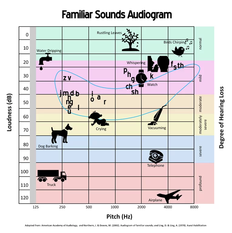
Because the human ear is capable to resolve a tremendously wide range of orders of magnitude of sound pressure, the Sound Pressure Level (SPL) was defined to assess the strength of an acoustic signal. This quantity is measured in dB (decibels), and that’s why you often come across dB numbers when buying products such as vacuum cleaners. In other words, the louder a sound (or the bigger its amplitude), the higher the dB value.
In addition to amplitude, the other fundamental characteristic of sound is frequency, which is measured in Hertz (Hz). Frequency quantifies the number of oscillations in one second, or how high or low-pitched a sound is.
But that’s not the whole picture… as we delve deeper into the world of acoustics there are a few more things to consider.
Generally speaking, the sensation of hearing is limited to a specific frequency range, between 16Hz and 20000Hz. Below 1500Hz there is a temporal delay of the signal at the two ears. Depending on the direction of incidence, the sound travels paths of different lengths to either ear. This leads to a phase difference in the signal at the two ears. Above 1500Hz the head causes a shielding effect, which produces a “shadow”. The ear canal forms a one-sided open tube, and this physiological circumstance is responsible for enhanced hearing sensitivity in humans in the frequency range between 3000Hz and 4500Hz.
At this point you might be wondering – Why should all this matter to engineers?
The challenge of psychoacoustics
It’s important to relate sound to human hearing capabilities and characterize it accordingly. When engineers are simulating and analyzing sound it’s important to keep this in mind, and this is where psychoacoustics comes in, with concepts like Loudness and Noise Weighting. Loudness is the subjective perception of Sound Pressure (mentioned earlier) and is measure in sones. The sensitivity of humans hearing to different sound frequencies is illustrated by the “Equal loudness Graph”.
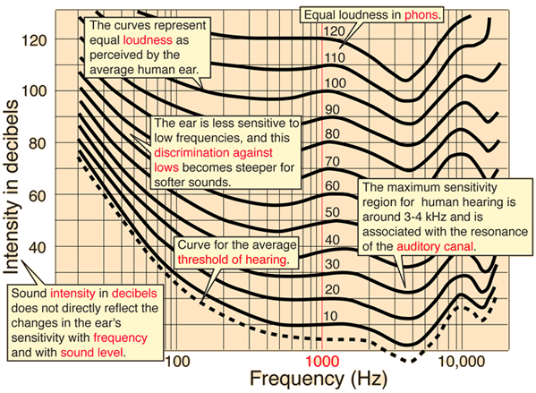
The lines on this graph each correspond to the Sound Pressure Level (SPL) required at various frequencies to be perceived as equally loud to a pure 1000Hz tone.
Just like Loudness, Noise Weighting is another psychoacoustics technique that allows us to characterize a measured sound by emphasizing the frequencies which are most important.
If you found all this interesting and would like to know more, our Simcenter Testlab team has some great videos which explain these concepts in more depth. Sound Quality Playlist
Better Aeroacoustics using Simulation
In order to cope with aeroacoustics engineering, simulation has turned out to be a viable tool. Like every simulation technique, also aeroacoustics simulation comes with the benefit of mitigating complex and expensive experiments and trial and error methods. If done right, aeroacoustics simulation hence has the potential to predict the aeroacoustics behavior of (noisy) products, make virtual design exploration studies and find better (quieter, more pleasing) acoustic solutions for many applications.
However, as the introduction has indicated aeroacoustics is a difficult discipline and hence engineers need a simulation tool that is capable of modeling the complexity of highly dynamic pressure waves.
For aeroacoustics engineering precise prediction of time-resolved turbulent fluid dynamics is a pre-condition. On top of that sits the simulation of aeroacoustics wave propagation to predict both amplitudes and frequencies with high accuracy. So simulating an aeroacoustics problem requires very specific models on top of just turbulent flow field predictions. And – while being able to capture those physics sufficiently accurately – such simulation tools need to be fast enough, so engineers can truly leverage them to find better acoustic solutions.
Aeroacoustic Simulation with Simcenter STAR-CCM+
Now, as a multiphysics Computational Fluid Dynamics CFD software tool, Simcenter STAR-CCM+ offers exactly that solution to allow engineers to run high-fidelity aeroacoustic simulations, fast and yet accurately. Over the years the breadth and fidelity of Simcenter STAR-CCM+ for aeroacoustics simulation has made significant progress, especially with the Lighthill and Perturbed Convective Wave models which were released in 2021.3 and 2022.1 respectively. And meanwhile, there is a wide breadth of acoustic applications Simcenter STAR-CCM+ is able to resolve while keeping the computational times at impressively low levels.
Simcenter STAR-CCM+ is able to simulate sound generation and propagation in fluid flows thanks to its acoustic models, each adapted to a different case scenario to suit most applications. To give you an idea, we will try to focus on 3 examples representing some of the most in-demand simulations that you can tackle right now:
Fan noise aeroacoustics simulation
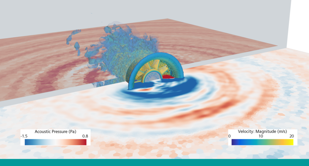
Whether it’s in your car, your laptop or your vacuum cleaner, simulating fan noise is becoming increasingly popular in order to make our devices quieter. The high-speed rotation of a fan poses an additional challenge to aeroacoustics simulation. Simcenter STAR-CCM+ offers a great solution that enables engineers across a variety of industries to assess fan noise.
Generally for rotating fans, there are two sources of interest when simulating fan noise: tonal and broadband noise.
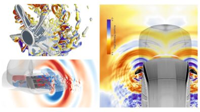
The tonal noise is due to unsteady loading on fan blades and shows up as distinct peaks on a Sound Pressure Level graph. Broadband noise is due to random unsteady fan blade loading and applies to the complete frequency spectrum. The image below shows how aeroacoustics simulation in Simcenter STAR-CCM+ is able to capture those inherently different types of sounds:
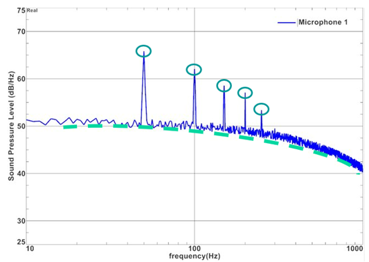
You can run this as an incompressible flow simulation with the new hybrid model, the Perturbed Convective Wave Model.
Coupling the predicted acoustic near field with the Ffowcs Willams-Hawkings analogy (FW-H) will also give you the chance to obtain far-field noise predictions. The FW-H model is an aeroacoustics analogy that is available in both Simcenter STAR-CCM+ and Simcenter 3D. The model calculates the far-field sound signal that is radiated from near-field flow data from a CFD solution. It’s a cheap method to predict far field noise on a specified FW-H receiver from either permeable or impermeable sound source surfaces. If the impact of mounting effects on the sound transport are negligible, Simcenter STAR-CCM+ can be used as a standalone product for the aeroacoustics simulation.
But you can do far more with Simcenter: the transient predictions from Simcenter STAR-CCM+ can easily be coupled with Simcenter 3D. This allows you to efficiently account for installation effects and far-field scattering.
The example showed above was taken from a paper written for the 2022 DAGA Conference, which outlines the Simcenter STAR-CCM+ numerical methodology and experimental validation of EAA’s axial fan.
HVAC duct aeroacoustics simulation
Heating, Ventilation and Air Conditioning (HVAC) systems are a very common source of noise in a cabin and have acquired more relevance as vehicles become quieter.
The aeroacoustics problem stemming from the HVAC duct can be tackled with the Lighthill Wave model (one of our newly released hybrid models) which is particularly apt at simulating far-field noise of incompressible fluids with low Mach numbers.
The Lighthill Wave model is one of the hybrid models for aeroacoustics simulation which has been ported to GPU with the release of Simcenter STAR-CCM+ 2210. We tried it on a simple elbow duct model consisting of around 7.6 million cells, and it took a little over 9 hours to run on one GPU card while it took 10.6 hours to run on 240 CPUs (equivalence calculated as 1 A100 = 276 CPUs).
Side mirror noise aeroacoustic simulation
Side mirror noise is an important aspect to consider when evaluating a mirror design for any vehicle. Any small ridges or wrong bezel angle and you could find yourself with a constant unpleasant loud noise in the front seats. It might be ok if you just drive around town, but you’ll realize soon enough as you get onto a motorway.
Our Automotive Application Specialist has developed a great template for side mirror noise aeroacoustic simulation, which allows customers to hit the ground running while greatly reducing setup errors.
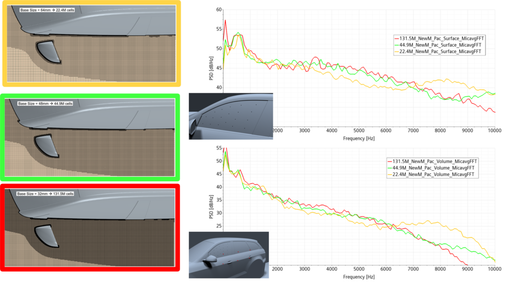
Thanks to the improved hybrid model recently developed (the Perturbed Convective Wave Model) and GPU availability, it’s never been easier to evaluate multiple designs in a shorter amount of time. Right now, the aeroacoustics simulation at hand takes about 71 hours on 400 CPU for a 54 million cells model to run, but only 33 hours on 4 GPU cards (equivalence calculated as 1 A100 = 216 CPUs).
Engineering a better acoustic world, decibel by decibel
There is so much more to learn and so many possibilities, it can be daunting to start working on an aeroacoustic simulation if this is not your usual field of work.
Hopefully this short introduction was a good first step into the world of aeroacoustics, and keep in mind this is just a fraction of the capabilities Simcenter offers. Thanks to Simcenter Testlab, Simcenter STAR-CCM+ and Simcenter 3D, we cover the full spectrum of acoustic analysis, from testing to aeroacoustic simulation and validation.
All this with one goal in mind: Give engineers the tools to make the acoustic world around everyone of us better. Decibel by decibel.
