Assess the thermal comfort in a city bus with a multi-zone modeling approach
Let’s see how the last version of Simcenter Amesim Embedded CFD can help you through a smart combination of 1D and 3D simulation environments.
Vehicle thermal comfort challenges
The need to assess thermal comfort in all kind of vehicles is constantly increasing due to climate changes but also to the resulting energy savings objectives. Especially to assess the thermal comfort in a city bus.
The electrification of vehicles also drives these energy saving. In these vehicles, heating is not “free” anymore, as it was for internal combustion powered vehicles, getting similarly to cooling its energy from the batteries, thus impacting the vehicle range.
In the transport sector consequently, OEMs as well as suppliers are facing the challenge of handling thermal comfort very early in the design cycle to make quickly the best decision in order to avoid inefficient late iterations.
Introducing thermal comfort assessment in early design should give the correct trends, quickly and easily, not going into too many details since all the system components are not finalized. It should be logically assessed for a large variety of configurations and realistic conditions, i.e. during transient scenarios.
To answer this challenge, we often use system simulation without offering however a sufficient level of fidelity, due to the 3D nature of air flow phenomena.
The classical alternative in doing it with a full 3D CFD approach is also not optimal since CAD needs to be fully available and number of configurations that can be quickly handled is limited.
Overview of Simcenter Amesim Embedded CFD 2020.2
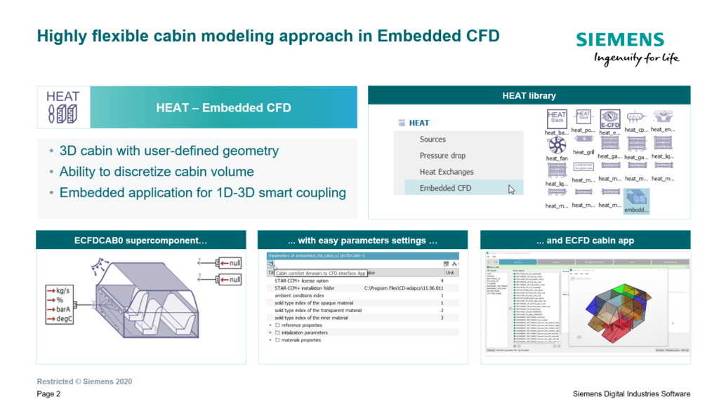
Considering the above-mentioned challenges, the Embedded CFD approach of Simcenter Amesim is de facto a good compromise combining the system simulation approach together with Simcenter STAR-CCM+ 3D CFD approach. Described as a hybrid tool between 1D and 3D CFD simulation environments, this tool benefits from both technologies. It offers the fidelity of 3D resolution together with close-to 1D simulation times, all encapsulated into an easy-to-use specific GUI.
The new 2020.2 version of Simcenter Amesim Embedded CFD for cabin comfort widens the possibilities. It can handle any type of cabin, ranging from a 2-seater car up to an entire commercial plane.
The user can now define its own geometry, the number of air zones, the location of air vents, the type of material (either opaque or transparent) and much more.
In addition to this important enhancement, we upgraded the compatibility with Simcenter STAR-CCM+ to additional versions (up to 2020.1).
Application to a city bus cooldown scenario with doors opening
A concrete scenario to assess the thermal comfort in a city bus with a multi-zone modeling approach will hereafter illustrate the usage of Simcenter Amesim Embedded CFD. Let’s simulate an entire bus cooldown in a first phase, followed by 2 consecutive bus stops during which both front and mid doors open.
Simcenter Amesim model
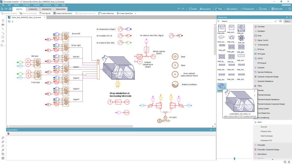
The figure below illustrates the HEAT library containing the Cabin component.
This component has 3 external ports by default to connect on the left side the air vents boundary conditions in terms of air mass flow, temperature, pressure and humidity and on the right side the vehicle velocity and ambient air temperature.
Build 3D geometry
To build the 3D geometry from the above Simcenter Amesim model, we launch the Simcenter Amesim Embedded CFD app from the cabin component.
The step-by-step GUI guides the user towards the completion of the 1D-3D coupled simulation.
Let’s start with the 3D geometry building.
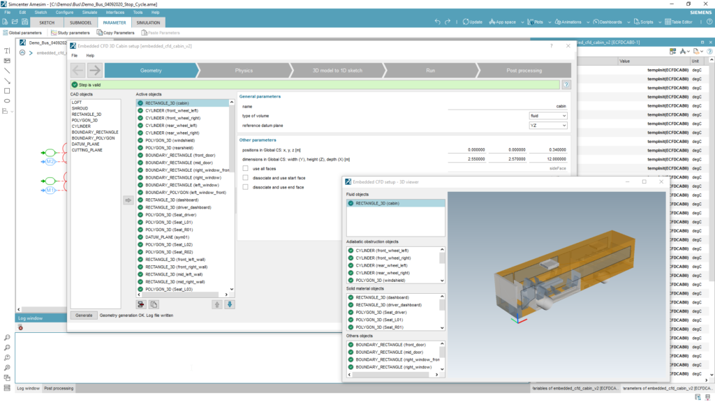
The 3D geometry is built with XYZ coordinates and dimensions of elementary blocks such as boxes, cylinders, 3D polygons, etc. … Elements can be of 3 types:
- Fluid: to create the fluid environment of interest (i.e. the resulting cabin air volume)
- Solid: to create objects that will be handled as solids exchanging heat with air
- Obstruction: to remove materials from the fluid domain (e.g. wheels)
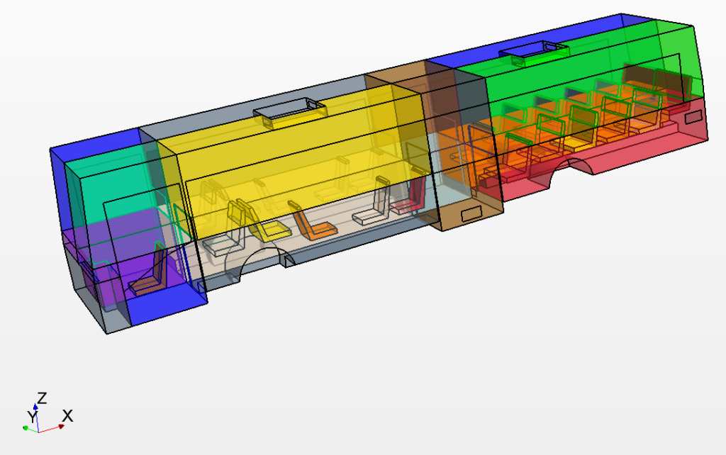
We use cutting planes to split the global volume into air zones of interest. For our bus model, we define a total of 16 air zones as seen below.
To help the user building the geometry, note that we associate a dynamic 3D viewer.
Once the geometry has been completed, the ‘Generate’ button silently triggers a Simcenter STAR-CCM+ model in few seconds.
Defining boundary conditions and meshing the 3D model
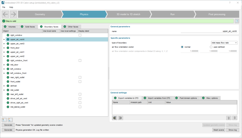
In a second step, we can perform several actions:
- Renaming elements (volumes and faces) from the geometry
- Associating boundary conditions to a face (see below figure)
- Associating variables to be exchanged between Simcenter Amesim and Simcenter STAR-CCM+ simply using drag and drop
- Defining the average Mesh size and allowing the handling of gravity
Simulating a transient scenario
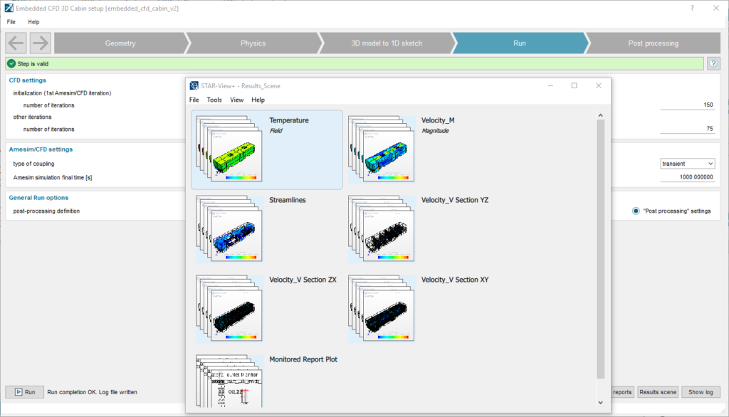
Before running the model, we generate automatically the 1D structure of the cabin during the ‘3D model to 1D sketch’ step. The user might have at the beginning of this step to redefine the dimension of the MUX element connected to the cabin.
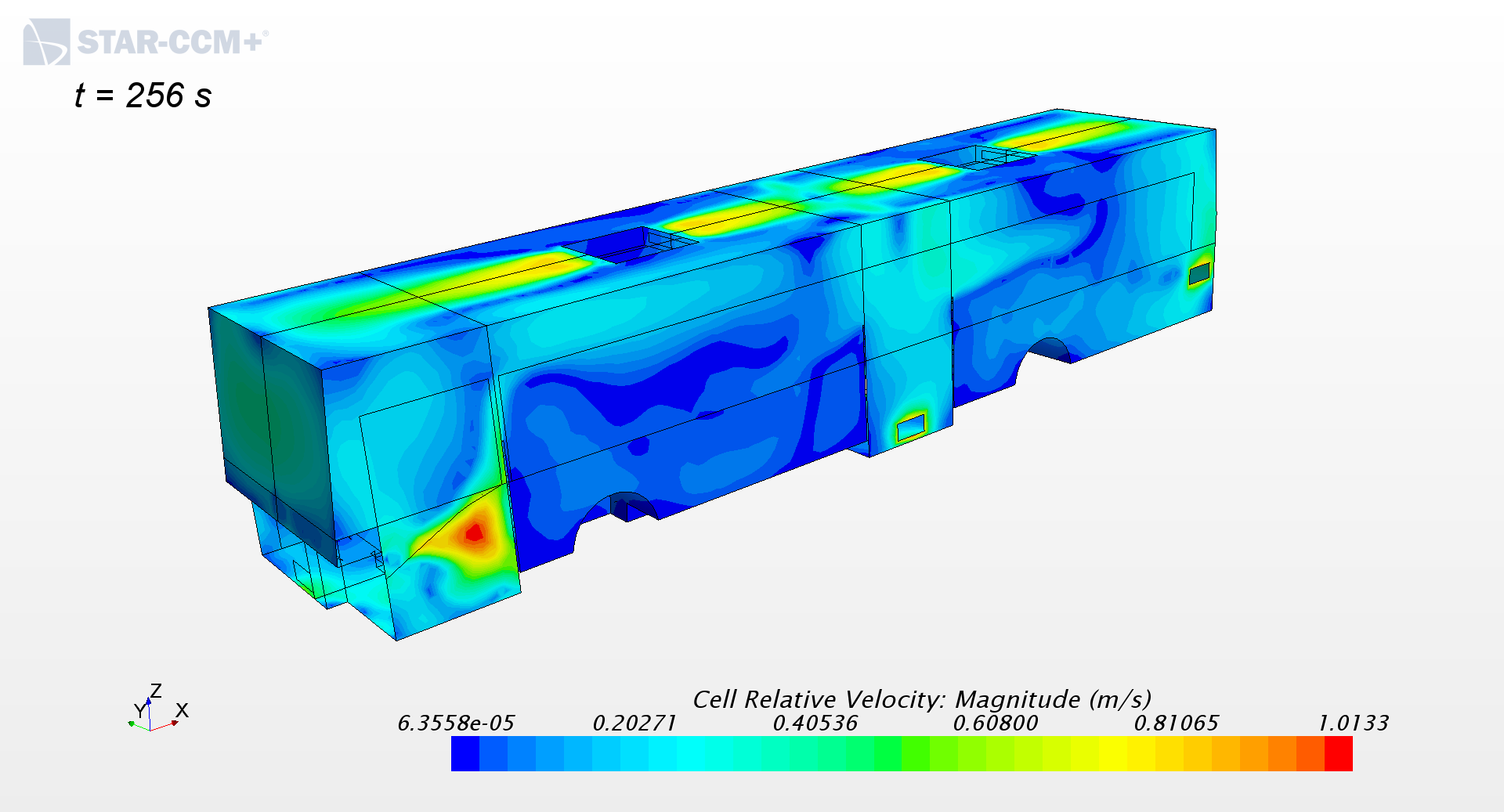
Once completed, the run can be defined and launched, and post-processed 3D results can be then accessed as shown on the figure below.
We can of course look also at transient results in Simcenter Amesim; the following picture shows the evolution of the 16 air zone temperatures during the cooldown.
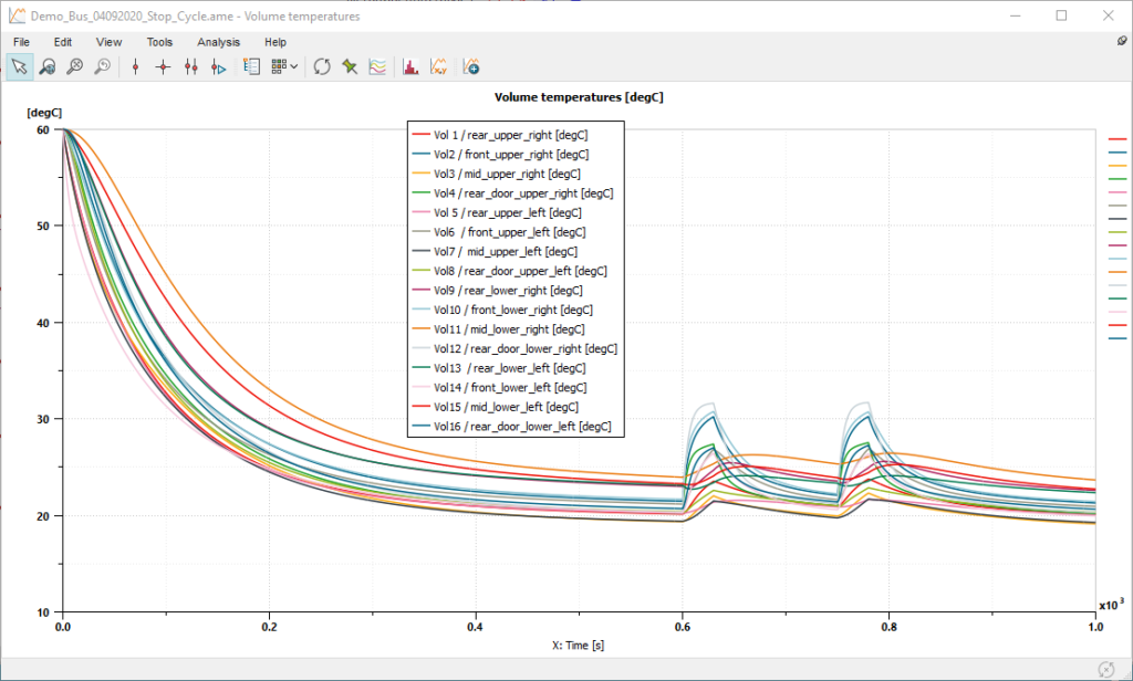
We clearly see the impact of the 2 bus stops after 600s with a 30s door opening each time.
Let’s now see more in details:
- How we couple Simcenter Amesim and Simcenter STAR-CCM+
- How we simulate the door opening
Details of 1D/3D coupling process
As part of the Embedded CFD workflow shown beforehand, we automatically generate the information exchanges between Simcenter Amesim and Simcenter STAR-CCM+ presented below. The user can add custom exchanges with Import / Export features.
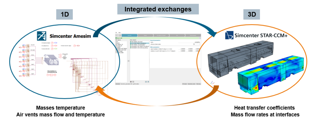
During the Simcenter Amesim transient, user-defined events trigger these exchanges as illustrated below.

Note that Simcenter STAR-CCM+ runs are performed as Steady-State calculations.
These events are associated with a Stop component and can be time-based or based on any system variable change.
In the example of the bus, there are 2 triggers:
- a time-based trigger with an increasing interval, so to be more accurate at the beginning of the cooldown
- a trigger linked to the bus speed, so to handle the doors opening and closing
The figure below illustrates the triggers:

Simulation of the doors opening
Let’s now have a look at the doors opening simulation.
In the scenario of our bus example, we set the ambient temperature to 35 degrees Celsius.
When the doors are opening during the bus stop, we apply at the doors a mass flow calculated from the air density difference. For that purpose, we need to get the air temperature and humidity from the air zones next to the doors as illustrated below.
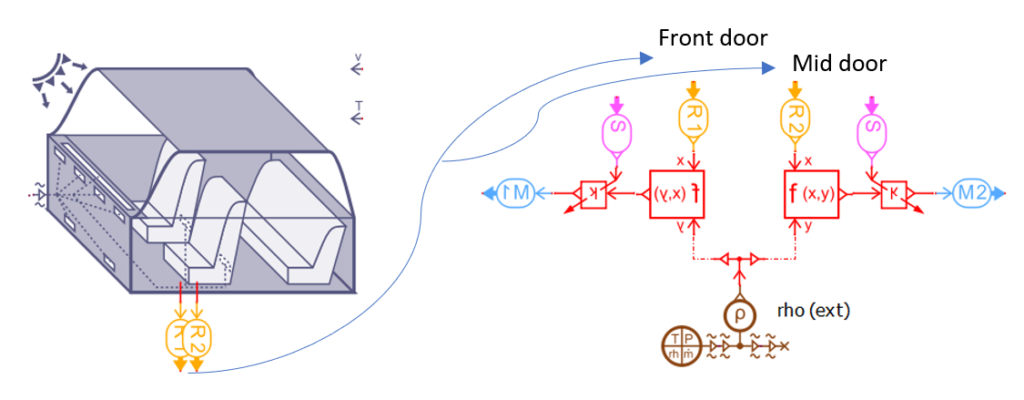
The analytical model used has been defined by Pham and Oliver [ref.]:

[ref.] Q.T. Pham, D.W. Oliver, Infiltration of air into cold stores, in: Proceedings of 16th International Congress of Refrigeration, vol. 4, 1983, pp. 67–72.
This results in the following mass flow profiles:

Note that the opening / closing is considered here as instantaneous, which can be of course adjusted to be more realistic.
We have demonstrated that Simcenter Amesim Embedded CFD is the right tool to assess the thermal comfort in a city bus with a multi-zone modeling approach, especially during early design stages for which decision making is essential.
We hope you’ve enjoyed the bus ride!
About the author:
Benoit Honel is a senior product manager electrification for Simcenter Amesim. He’s addressing the challenges of multi-physics simulation for electrified vehicles in the automotive and aerospace and defense industries. His main activities include the thermal management and system integration of batteries, power electronics, electric machines as well as fuel cells. He’s also focusing on workflows and coupling frameworks between Simcenter Amesim and electrification-related 3D tools of the Simcenter portfolio.
Want some more?
Want to learn more about Simcenter combined solutions for cabin thermal management strategies evaluation? Register for the on-demand 3 Part Webinars Series.
Watch this video to learn how to optimize vehicle thermal comfort using the Embedded CFD Cabin capability of Simcenter Amesim:
Need to install the latest version? Contact your local support office.
Stay tuned to discover our upcoming release of the Simcenter Amesim 2020.2 version and check our blog to read on related topics!
