Combine solution speed and accuracy for axisymmetric rotor dynamics

In a previous blog, we explained how centrifugal loads may lead to high levels of vibration (and even system instability) when a rotating structure is not axisymmetric. We also gave some examples of situations that could be life-threatening. But in fact, you’ve all seen this phenomenon in your daily lives already. At least if you’re a grown-up, and you’ve already filled a washing machine with clothes by yourself. Don’t be scared though, your washing machine is not going to kill you. But the more axisymmetric it can operate, the more efficient it will run and the longer it will last.
For rotor dynamics simulation, axisymmetry is an opportunity. In this blog post, we will explain how you can exploit it to reduce model size and optimize computational requirements, while keeping accuracy. We will also demonstrate which techniques are available in Simcenter 3D for axisymmetric rotor dynamics, and how they can benefit you.
Reducing model size for axisymmetric rotor dynamics
Take this axisymmetric rotor dynamics model, mounted on bearings, as an example. The structure can obviously be represented by its 3D components, meshed with 3D solid elements. But interesting modeling alternatives exist.
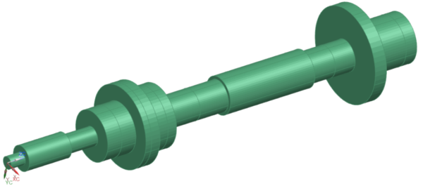
2D rotor modeling with Fourier harmonics
Since the model is symmetric around the rotation axis, representing (and meshing) the axisymmetric portion in the meridian plane should actually be sufficient. Because during the calculation, expanding the displacements field in Fourier series can account for 3D effects. Such a representation is called a 2D axisymmetric model enriched by Fourier harmonics, or in simpler words: 2D Fourier model. In this case, each node has more than 6 degrees of freedom. It is a perfect alternative to a 3D model for this particular structure.

1D beam modeling
A next degree of reducing model size is a 1D beam model with equivalent cross sections and concentrated masses with the equivalent inertia properties. However, although this representation is accurate enough for various types of applications, it has certain limitations. It does not describe disk flexibility, for example.

Saving computational resources is always a tempting opportunity. But keeping accuracy is obviously essential. So, let’s have a look.
Comparing the methods
With the above models that all represent the same rotating system, we calculated the critical speeds for 2 sets of backward and forward modes. The result of this is compared to a theoretical reference in table 1 below [1]. It shows that the results of all 3 model variants correspond very well to the theoretical reference.
| Critical speeds (rpm) | Theoretical reference | 1D beam model | Percentual difference to reference | 2D Fourier model | Percentual difference to reference | Full 3D model | Percentual difference to reference |
|---|---|---|---|---|---|---|---|
| Mode 1 | 15502 | 15383 | 0.77% | 14969 | 3.44% | 15218 | 1.83% |
| Mode 2 | 17169 | 17016 | 0.89% | 16811 | 2.09% | 17046 | 0.72% |
| Mode 3 | 46951 | 46718 | 0.50% | 45994 | 2.04% | 46556 | 0.84% |
| Mode 4 | 50254 | 49949 | 0.61% | 49543 | 1.41% | 50015 | 0.48% |
Figure 4 shows the corresponding modes.

If logic would be respected, you should see the accuracy improve as the model gets more details (so 3D>2D>1D). But even that doesn’t show in this particular example. That’s because all methods are perfectly suitable. The small differences you see in the table in this case are rather on the level of parameter choices and discretization. If there would be a real problem related to the assumption of symmetry, you would observe a significantly larger error.
Hybrid modeling, a flexible approach for optimal model size
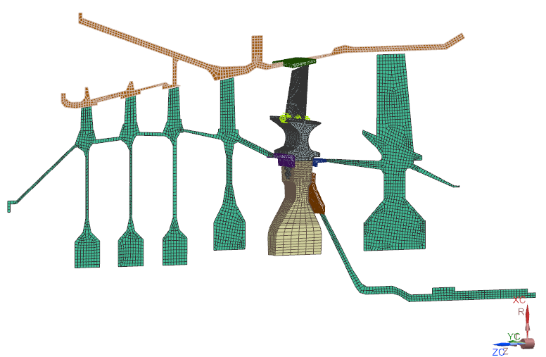
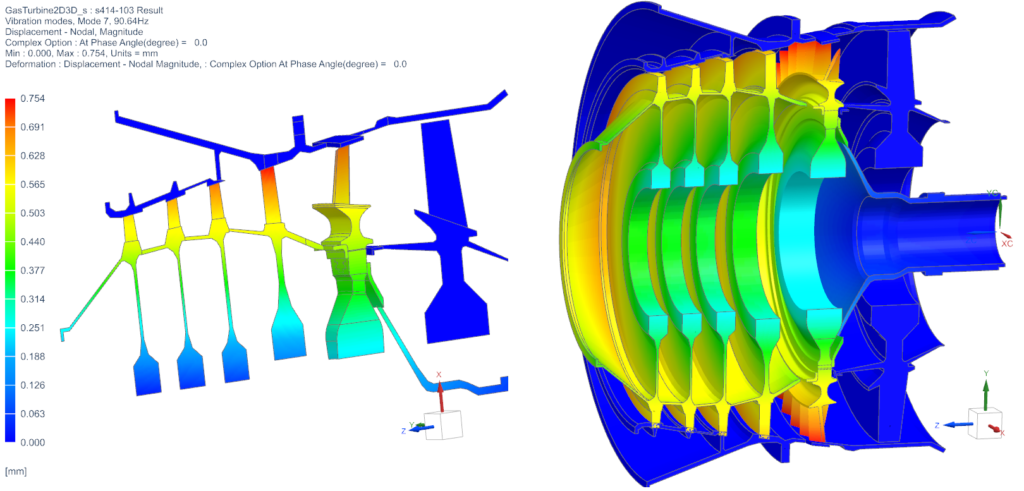
For such cases, there is an in-between solution. Because in Simcenter 3D, we can combine modeling approaches for axisymmetric and non-axisymmetric rotor dynamics. Then engineers can then choose the representation for each part individually. We illustrate this in figure 5. Part of the gas turbine is axisymmetric, but the blades are not. Engineers can then model for example the axisymmetric part with 2D Fourier elements while keeping the blades in 3D or modeled by cyclic symmetry sectors. Simcenter 3D facilitates such hybrid modeling options through dedicated connections at the interface between the 2D and 3D models. Figure 6 shows how the results can still be shown on a full 3D model.
Reduction by superelements
Besides the interesting (and in some cases necessary) reduced modeling techniques presented above, Simcenter 3D can also include superelements in axisymmetric rotor dynamics simulations.
What are superelements?
The vibrations that are studied in rotor dynamics analyses yield relatively small deformations. So, the rotating part usually behaves linear. It’s only in connections where nonlinearities occur. The bearings, for example, are not symmetric, contain oil, and their properties usually vary with the rotation speed. So, if we would focus on the linear rotor model (disregarding the bearings), we could imagine it’d be replaced by a reduced model using a Component Mode Synthesis (CMS) technique. This is what we call a superelement. It is made of modes and matrices on selected nodes. Those are the stiffness, mass and damping matrix, as well as the gyroscopic matrix that takes the rotor’s rotation into consideration. If the superelement is calculated in a rotating reference frame, the Coriolis matrix is also added.
A superelement is linear. But it can also be generated for nonlinear models, for example around an equilibrium position for a given rotation speed. The condensed model generated in this way is then valid in this configuration only, and matrices are then tangent matrices.
Which models can be condensed in a superelement?
That question has a simple answer. Because any model can be condensed in a superelement: a 3D model, a 2D Fourier model, a 1D model, a cyclic symmetry model, rotating or not, symmetric or asymmetric.
Replacing the stator and/or the rotor by a condensed equivalent model leads to great time savings. It drastically reduces the size of the problem to solve, especially in a transient nonlinear analysis. Then after calculation, results can be recovered on the original model for postprocessing purposes.
How great is the benefit of model reduction?
Now that we’ve described all the model reduction capabilities in Simcenter 3D for axisymmetric rotor dynamics, let’s see how they can benefit you.
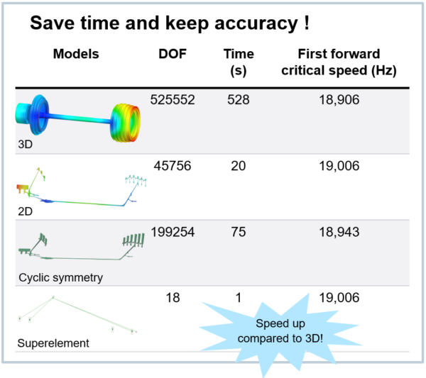
In the table below, we compare the calculation times of various reduction options for the case of the low-pressure rotor, simulating critical speeds using complex modes. As you can see, the ultimate reduction cuts the problem size (number of degrees of freedom) by a factor or 30.000(!) and the computation time by a factor of 528(!) while still delivering quality results.
How to handle non-symmetry in rotor dynamics simulations?
The rotor is not symmetric, but the stator is
Axisymmetry of the rotor is the basis for rotor dynamics equations. However, this hypothesis doesn’t hold for many industrial applications, for example a jet engine made of blades. For such cases, it’s advisable to model the rotor as a non-rotating component and take the effects of rotation into consideration in the form of centrifugal loads and Coriolis effects. This is then equivalent to solving the rotor dynamics equations in a coordinate system that rotates with the rotor. When doing so, you actually place the observer in a rotating reference frame, where the rotor is seen as non-rotating and the stator as rotating. This obviously only works if the stator is axisymmetric, and the bearings isotropic.
Both rotor and stator are not symmetric
Let’s consider another example: a helicopter. Because that one has rotor blades that cannot be considered as axisymmetric with respect to the rotation axis. But the fixed part, the fuselage, is also far from symmetric.
To comply with the rotor dynamics theory, the rotating part – as it is not symmetric – must be considered as not rotating. This is possible in a reference frame that rotates with the rotor and by adding centrifugal loads and the Coriolis effect. The fuselage is also not symmetric and has to be solved in a fixed reference frame.
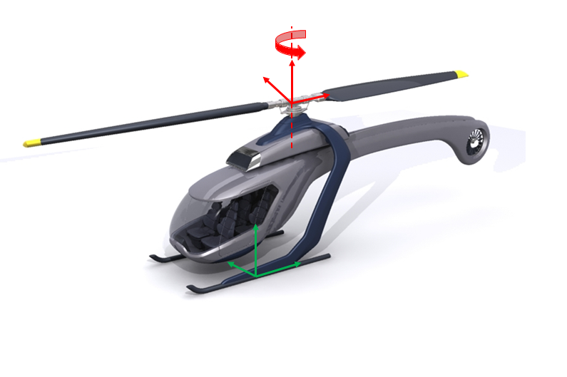
In Simcenter 3D Rotor Dynamics, it is possible to solve such a fully non-symmetric rotating system by using a transient analysis. And because this one is nonlinear, and often requires fine time steps, the application of model reduction techniques can be necessary. This capability in Simcenter 3D is unique.
An example
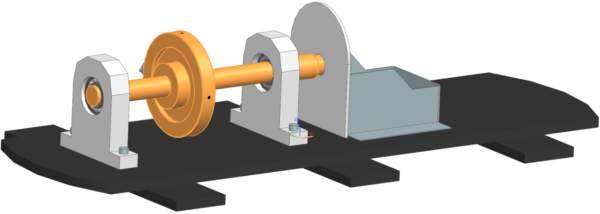
Let’s illustrate the above with an example where a rotor is connected to a stator through bearings. Our goal is then to study the forced response of the full system to an unbalance on the rotor: a deviation of the disk’s center of mass by 5mm and 10 grams.
The model setup
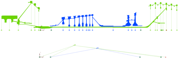
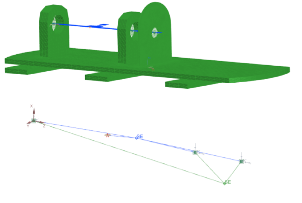
To do so, we create a superelement for the stator (in green) in the fixed reference frame containing the fixed boundary conditions. For the rotor (in blue), we create a superelement in the rotating reference frame. And retained nodes are defined at the locations of the connection elements, where the bearings are in the final assembly; and at the location of the unbalance mass (center of the disk).
You can see the finite elements and their superelement representations in the picture below. To separate the rotating part from the stator part, there is a dedicated element between the bearing and the rotor. This one allows the solver to compute the stator in the fixed reference frame, and the rotor in the rotating reference frame.
The results
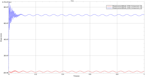
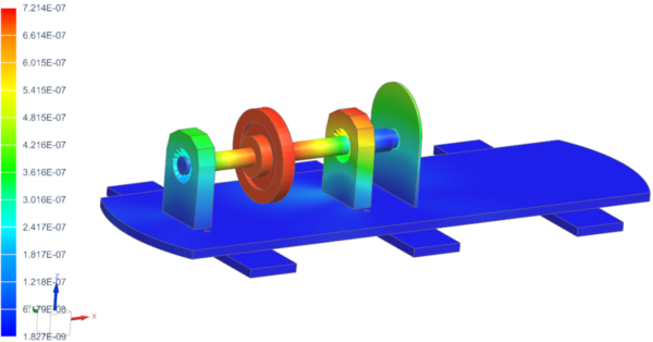
In the display below, you can see the displacement at the unbalance node for a constant rotation speed of 500 rpm. Unbalance load in a rotating reference frame is seen as a static force. That is what we observe as a constant displacement in the Y-direction and as minor vibrations.
In summary
Simcenter 3D Rotor Dynamics offers many possibilities to solve your rotating system. By exploiting symmetry, you can greatly decrease problem size and computation time, while still getting quality results. And each part/component can have a tailored reduction, all in one model.
Simcenter 3D also has unique features to bypass the constraint that rotor dynamics equations are only valid for axisymmetric models. And also non-symmetric assemblies can be handled by combining calculations in the fixed reference frame for the stator, and in the rotating frame for the rotor.
All these capabilities for axisymmetric and non-axisymmetric rotor dynamics are available in Simcenter 3D 2021.2.
Related blogs and other information on rotor dynamics
Did you enjoy reading and want to know more? Then you might consider reading the following blog posts and other resources as well:
- Rotor dynamics: when accuracy is a matter of life and death
- Bearing modeling makes or breaks rotor dynamics simulation
- Rotating systems – Tune your intuition
- Solution Guide: Simcenter 3D for structural dynamics
References
[1] Nelson, H.D. and Mac Vaugh, J. M., The Dynamics of Rotor-Bearing Systems using Finite Elements, J. Eng. Ind. (ASME), 593-600 (1976)
