The impact of bumpy rides: making sure your EV battery survives rough roads
Introduction
Electric vehicles are at the center of today’s developments in the automotive industry, and as the heart of an electric vehicle, the battery plays a pivotal role in powering the vehicle. It’s a crucial and valuable component. However, its significance goes beyond functionality only – the battery’s weight, cost, and vulnerability to damage make it an area of concern for EV owners.
In contrast to vehicles with internal combusting engineers, electric vehicles often have the battery integrated in so-called skateboard platforms which are popular in the automotive industry as they integrate the battery pack into the vehicle’s floor. This design provides numerous advantages but also poses significant risks for electric vehicle owners. With the increasing prevalence of speed bumps on our streets, there is a growing concern about the potential damage these obstacles can cause to the battery pack located underneath the vehicle. Carelessly traversing a speed bump at high speeds can result in expensive repairs or even the need to replace the entire vehicle.
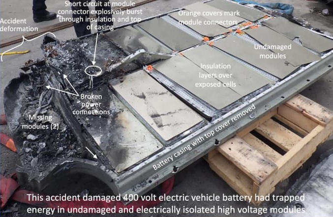
In a press article published by Reuters Information in March 2023, Christoph Lauterwasser, the managing director of the Allianz Center for Technology, emphasized the increasing number of battery damage cases and underscored the importance of handling batteries with utmost care. The repairability of battery packs has become a critical consideration for automakers, with some, like Ford Motor Co. and General Motors Co., focusing on making repairs easier. However, Tesla Inc. has taken a different approach, introducing a new structural battery pack in their Texas-built Model Y that experts have deemed “zero repairability”.
The impact of battery damage extends beyond individual vehicle owners. Even prominent car rental companies like SIXT and HERTZ have seen a decline in the number of electric vehicles in their rental fleets due to the high repair costs associated with battery damages, particularly those resulting from collisions. This information, reported by Reuters in January 2024, highlights the significance of protecting EV batteries to ensure their longevity and minimize repair expenses.
In this blog, we will have a closer look at the challenges and solutions surrounding the protection of your EV battery. Using Simcenter Amesim, we will demonstrate how you can better understand the risks posed by collisions and bumpy rides and explore strategies for safeguarding this critical component.
Battery modelling in Simcenter Amesim
Simcenter Amesim offers very valuable capabilities when developing and integrating components in electric vehicles. It allows you to assess key performance characteristics like range, vehicle performance, thermal performance and battery lifetime. In this blog, we will show demo models developed in Simcenter Amesim that help to analyze the impact of an electric vehicle’s battery on a speed bump, depending on the velocity of the car and the height and shape of the bump.
Virtual proving ground
The test ground is generated using the Ground Designer tool and the battery pack of the skateboard platform is meshed using mesh-sphere contact submodels. Speed bumps are increasingly used to ensure low speeds in urban areas. Depending on the country, they have many shapes, heights and widths; several standards exist and are more or less respected. The test ground used in this demo includes 3 types of speed bumps:
- Semi-circle speed bumps
- Sinusoidal speed bumps
- Trapezoidal speed bumps
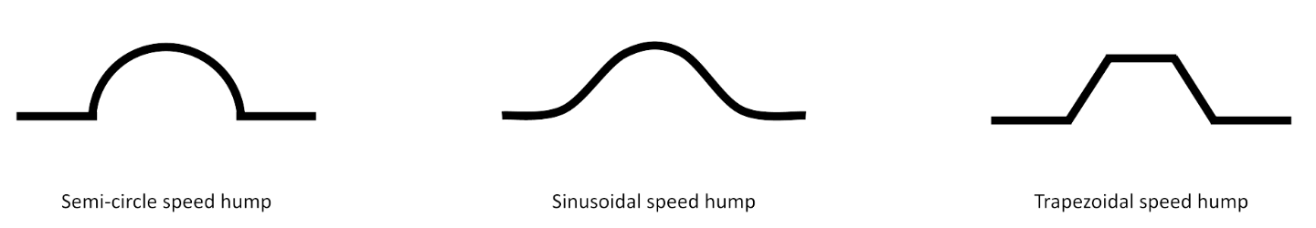
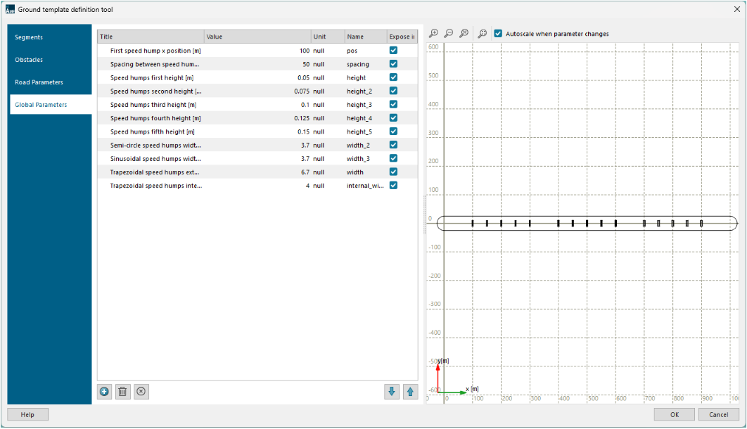
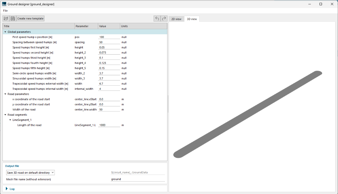
For each speed bump type, 5 different heights are tested: h1 = 5 cm, h2 = 7.5 cm, h3 = 10 cm, h4 = 12.5 cm and h5 = 15 cm. This test ground is then created in Simcenter Amesim using the embedded ground designer app.

Several parameters are exposed in the ground designer app, giving the possibility to modify certain parameters of this proving ground.
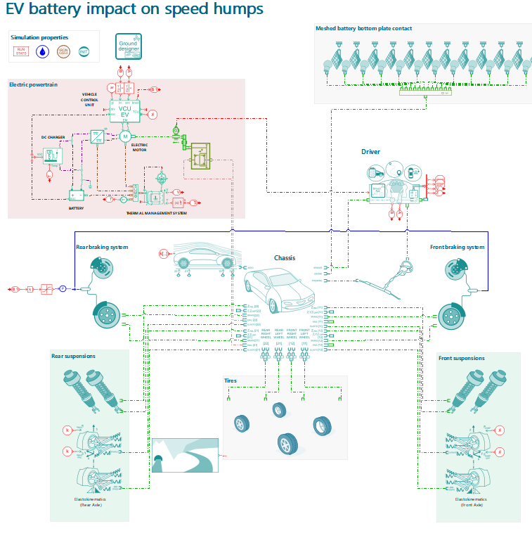
Vehicle model
The electric powertrain is modeled using the IFP Drive library and the chassis model uses mainly the vehicle dynamics library components.
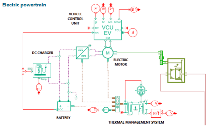
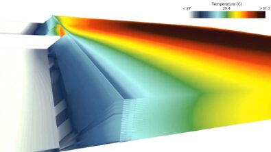
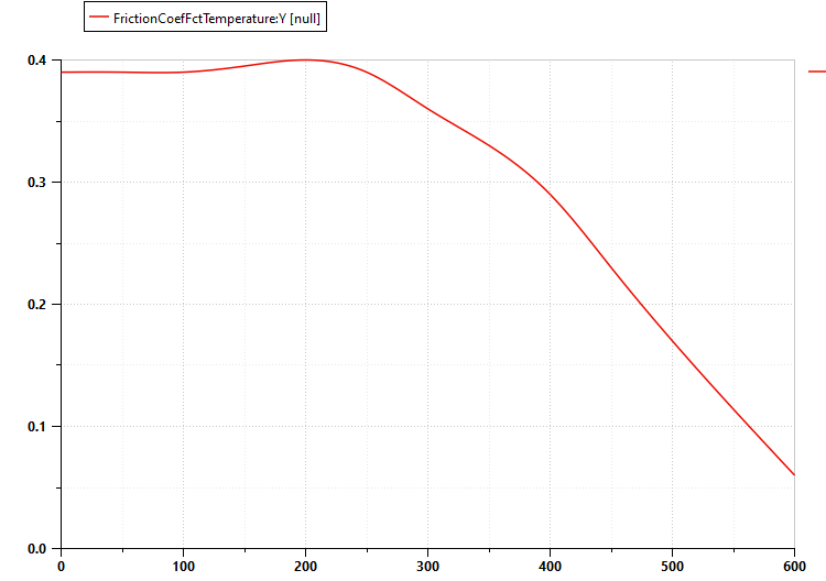
This model includes a VCU, the electric motor, the battery system, a charger and a simple thermal model of the battery and its cooling system. The braking system includes a simple hydraulic system and a basic thermal model. The friction coefficient is calculated as a function of disc temperature using the following table:
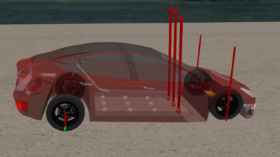
The final model sketch includes a detailed chassis 15 DoF model of Tesla chassis and Pacejka tires models. The new automatic tuned driver model will follow the trajectory on the defined bumpy ground.
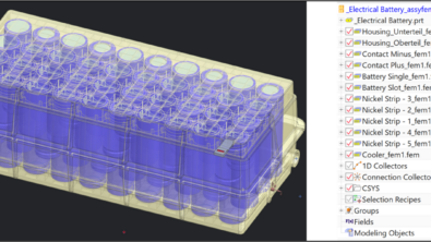
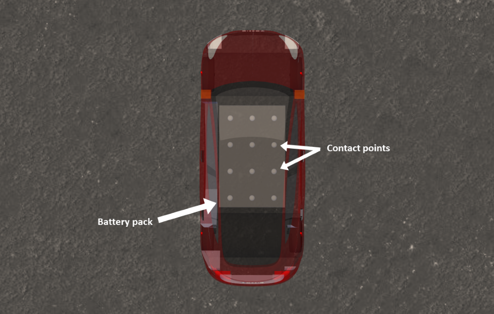
Integrated battery pack
The battery pack is meshed using 12 mesh-sphere contacts. These contacts form a very simple grid to mesh the battery pack, as shown below.
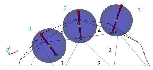
The contact detection uses the (BVH) Bounding Volume Hierarchy approach. The first contact detection is at the (BV) Bounding Volume level. If a contact appears between the BV of the sphere and the end BV of the BVH, a contact detection is computed between the sphere and the triangle inside the end BV. The next picture shows 3 spheres in contact with one or several triangles.
- The sphere 1 has only 1 plane contact with triangle 1
- The sphere 2 has 5 point contacts with triangles 1, 2, 3, 4, and 5
- The sphere 3 has 2 segment contacts with triangles 3 and 4
- Each sphere has only one reaction force
Results
The Tesla is then driven on the test ground at five different speeds:
- low speed: 5 m/s (approximately 18 km/h or 11 mph)
- normal speed: 10 m/s (approximately 36 km/h or 22 mph)
- high speed: 15 m/s (approximately 54 km/h or 34 mph)
- very high speed: 20 m/s (approximately 72 km/h or 45 mph)
The first three speed profiles are not totally constant to more accurately define the behavior of a human driver when approaching a speed bump. If the vehicle travels at 5, 10, and 15 m/s over the bumps, it goes faster on the flat sections, it brakes before passing the bump and accelertes just after (see curves below).
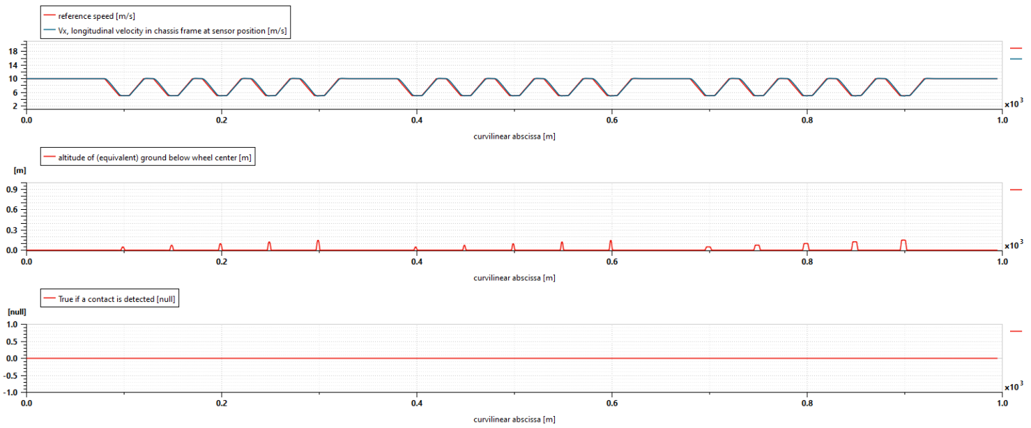
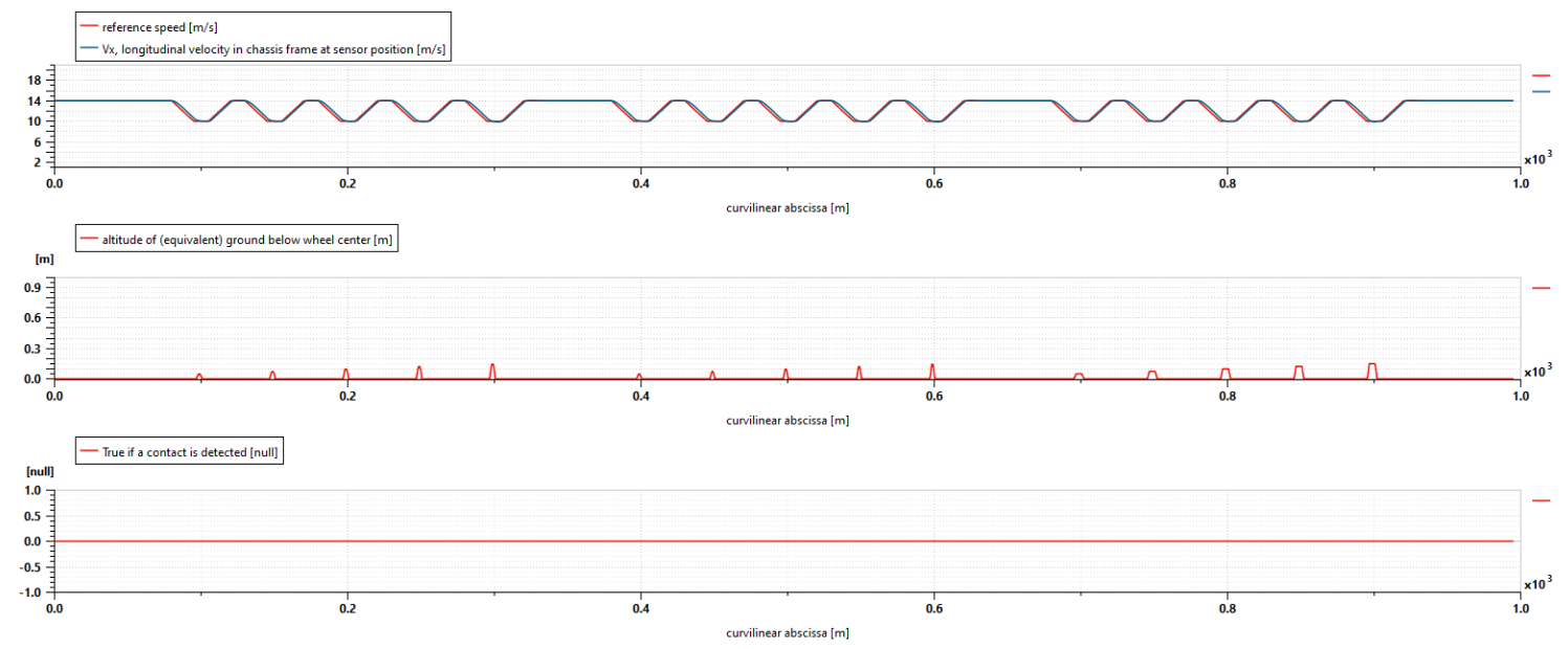
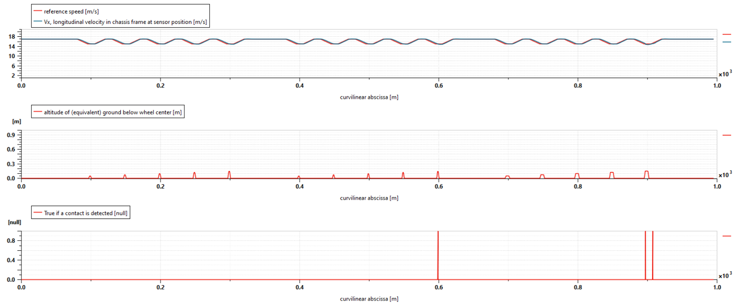
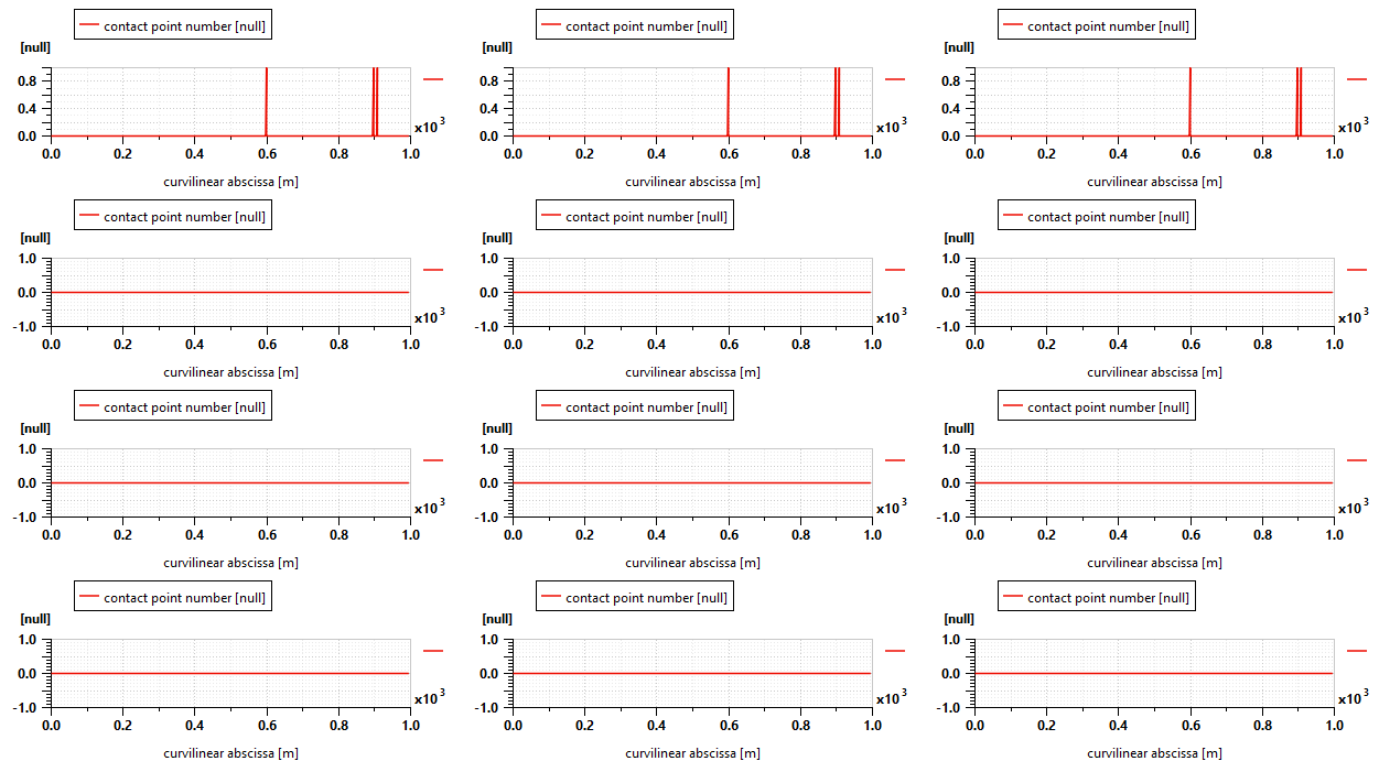
Several plots are created to study the behavior of the vehicle. The mesh-sphere contact submodels include a “contact point number” variable which can be used to monitor the occurrence of a contact. By summing this variable for all contacts, it is easy to detect whether the battery has hit the ground, as the sum will be greater than 0. For low speed and normal speeds, one can observe that the battery doesn’t touch the ground. By contrast, when speed exceeds 50 km/h or 30 mph, i.e. the usual speed limits in urban areas for many countries, one can observe that some contacts are detected while driving on the highest speedbumps.
Other plots can be used to locate these contacts. One can clearly see that the most affected area is the front of the battery pack. This kind of study can help to identify the weakest points of the battery and position reinforcement plates.
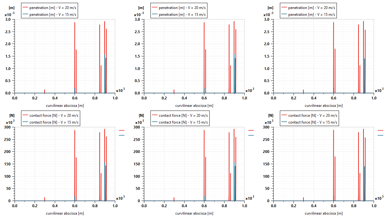
Finally, the mesh-sphere contact submodel enables the estimate of contact force and penetration during the impact in order to determine whether the battery pack would be severely damaged, as well as to size reinforcement plates. As an example, here is a comparison of penetration and force on the front of the battery pack between 15 m/s (in blue) and 20 m/s (in red).
A 3D Animation helps the user visualize where the contact points on the battery pack occur.
Conclusion
This blog demonstrates how the multiphysics simulation capabilities from Simcenter Amesim can help automotive engineers analyze the possible contact shocks against the battery pack, depending on different chassis designs. The couplings on the same simulation sketch of the chassis, the powertrain, and the battery pack geometries allow us to have the right virtual analysis of the damage caused. Some modular, split battery modules with reinforced walls on some battery pack parts could be defined using this simulation model. As the next step, engineers could consider designing active suspension systems using ADAS sensors and controllers to change the stiffness of the suspension. After the detection of the obstacle (speed bumps, potholes…) by cameras or lidars, the ADAS controllers will interact with the active suspension sub-system to increase the stiffness just before the bump to avoid damage to the battery. All of this is possible with Simcenter Amesim.
Want to try out Simcenter Amesim for yourself? Sign up for a free 30-day online trial!