Tank sloshing simulation. Slosh my world!
Tank sloshing simulations on an industrial development timeline? Impossible… or?
The other day, curiosity pushed me to read articles and papers about tank sloshing simulation of satellite’s fuel tanks. The strong coupling between the liquid propellant motion in the spherical tank and the solid deformation of the solid membrane is fascinating. Fluid Structure Interaction (FSI) can be challenging to simulate as two types of numerical solvers and technologies (fluid with finite volume and solid with finite element) need to communicate and converge together toward the solution.
However, some conclusions of some recent papers shocked me. They stated that such simulations were too troublesome and that the tools were not efficient enough to provide results in an industrial timeline. As an application engineer for Simcenter STAR-CCM+, I use this tool daily for multiphysics applications among them: FSI studies. Maybe they did not use the right tool for this type of analysis, a bit like using a hammer on a screw, you will end up nailing the screw but at the price of much more effort, accuracy and time wasted than you would if you used a screwdriver. I was then eager to solve this challenging study with Simcenter STAR-CCM+ ‘s embedded FSI capabilities to make the most out of it.
First simulation: Just a tank
Based on a NASA publication, I started to reproduce the test bench setup with a tank sloshing simulation using the little information shared there. A sinusoidal lateral displacement stimulates the tank over three periods. It then rests to witness the natural damping of the system.
I decided to work on a full scale one-meter diameter tank filled up to 60 percent. The excitation period is 1.5 seconds. The first simulation I created had no solid membrane to use it as reference.
The oscillations take quite a while to vanish as only viscosity dissipates energy here.
Adding a hyperelastic membrane
Similar to the study in the paper, I am starting simple with a flat membrane. It is made of SIFA-35, a hyperelastic material used for aerospace tank diaphragms. The solid part is added to the tank sloshing simulation. In a few clicks, a two-way coupled FSI simulation is now setup in Simcenter STAR-CCM. This means that the pressure of the fluid deforms the solid part and this displacement morphs the mesh to affect the fluid back.
Within 3 hours on six cores of my workstation, I could get results correlating well with the NASA screenshots.
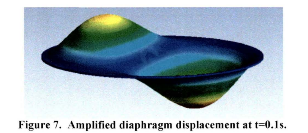
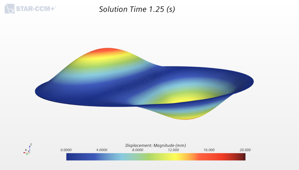
Then, I just moved to a more realistic membrane crater shape. A few hours later, results were available:

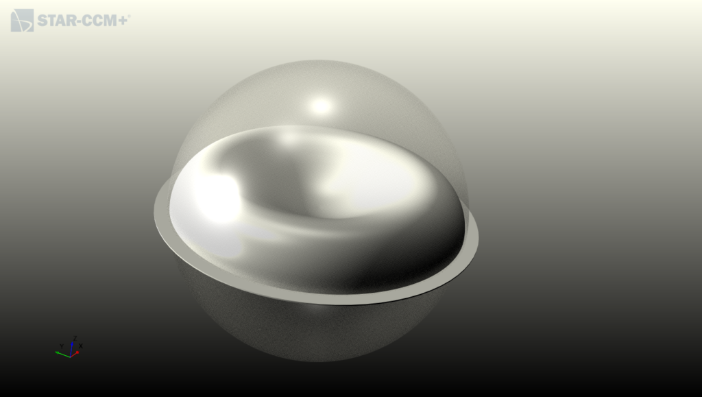
Crater shape membrane sitting in the spherical tank before the sloshing 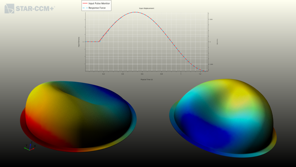
Amplified crater shaped membrane displacement during the sloshing obtained with a Simcenter STAR-CCM+ FSI simulation
I was slightly disappointed that the membranes were efficient to damp the motion and so not much was happening. But it proved that with the right tool, FSI simulation can be conducted satisfactorily. Within a reasonable time, both CFD and structural solvers converged inside a common program.
Pierced membrane for a satisfying visual
To satisfy my quest of a more exciting sloshing case, I modified the case of the flat membrane and added some holes in it. Like this, there is not any physical separation between the gas and the fluid. In this configuration, I was expecting much more to happen in this FSI simulation: membrane moving, bubbles and liquid jets… And this time, it did not disappointed me:
FSI everywhere!
No doubt, Satellites and tank sloshing are fascinating engineering examples, but you don’t have to go to outer space to explore the world of fluid structure interaction. Have you e.g. ever thought about bridges under heavy wind, or your very own heart?
