What’s New in ST10: Clone Components

Each of the past couple of releases of Solid Edge has seen some enhancement in the patterning, copying, and/or placement of additional occurrences in assemblies, such as Replace Part, Duplicate Component, and Along Curve. These have all been great productivity enhancements to the already great assembly environment in Solid Edge. The addition for ST10 is Clone Component.
 Art Patrick is the planner for new assembly functionality, and here’s what he has to say about Clone Component:
“Clone component placement in assembly is a productive way to position components that have a common relationship scheme. This reduces the tedious work of placing the same component over and over at different locations in the assembly.”
Remember that “component” can be a part or subassembly, or multiple parts/subassemblies. Plus, since this feature uses geometry recognition, it doesn’t require that you have ordered pattern features, you can use synchronous or imported parts as the basis for positioning the parts.
I find it’s always best to use my own stuff to demonstrate functions. Anybody can copy images and text out of the What’s New docs, but to really show what the new 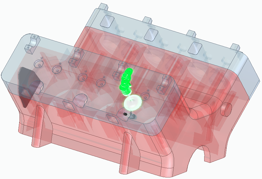 command is capable of, I’ll use it on something I built years ago, and it is even imported, just to drive home the fact that you don’t need active features to make this work. The example assembly is of course my engine assembly. Having put this together myself, I know that assembling the rocker assembly is a major pain in the backside. So I’ll use Clone Component to position the rocker assembly, valve and spring. If you look at the assembly, you’ll notice that there are two cylinder heads, so the components must go onto two different parts in multiple locations.
I’m using screen shots of the command bar in its most verbose configuration, just so you can see labels for all of the buttons, especially for new users. Truth is that I work with Solid Edge this way (via the Maximum  Assistance theme).
Anyway, the workflow for Clone Component is:
- Select Clone Component button
- Select the parts or subassemblies you want to pattern
- Select the faces (on a non-patterned part) that the original parts mate to
- Select the parts where you want Solid Edge to search for similar faces
I started off with my engine block (red), cylinder heads (gray), and rockers/valves. In the Select Components step, I picked the parts from both the Pathfinder and the graphics window. Right click to accept the selection, or Ctrl-select to remove a part, or Deselect to clear the selection.
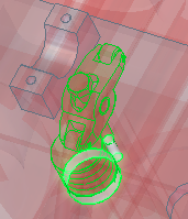
In the Select Faces step, select the cylindrical faces that the valve and spring are seated in. These are called reference faces.Right click to accept.
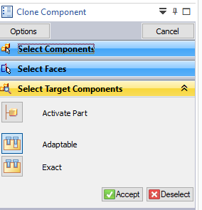
If you get messed up while working through the steps, look to the prompts on the prompt bar at the bottom 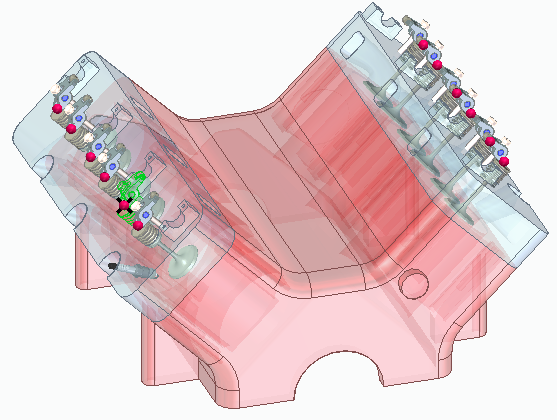 of the display. In the Select Target Components step, the Prompt bar says “Click on targe components to search for reference geometry. Right-click or Enter to accept.” So lets move on and select the target components.
The Select Target Components step wants you to pick the parts where the geometry recognition will find equivalents for the reference faces you picked in the previous step. In this case, I select the two gray cylinder heads and click Accept.
Notice that the Clone Component command has populated all rockers, two per cylinder, on two separate cylinder heads. We started with a selection of components in the second position if we were using patterns to do this, but again the function uses geometry recognition, so there are no regular patterns involved, and the cloned 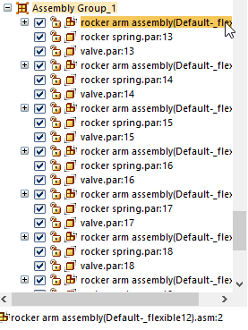 components could have any random orientation, as long as they are mated to faces similar to the selected references faces which are part of the target components.
The result is an assembly group in the pathfinder where the instances of the original components are separately mated to the target components. Individual mating enables these instances to be used for motion, or shown in different positions.
This is well thought out functionality, and I’m glad to see it finally released in product headed to end users.
