Solid Edge Tips and Tricks from Forum Users #25
An assortment of short tips and tricks based on the discussions in the Solid Edge forum.
Due credit is given to respective contributors.
First, a quick list of the previous compilations:
T&T #01, T&T #02, T&T #03, T&T #04, T&T #05
T&T #06, T&T #07, T&T #08, T&T #09, T&T #10
T&T #11, T&T #12, T&T #13, T&T #14, T&T #15
T&T #16, T&T #17, T&T #18, T&T #19, T&T #20
T&T #21, T&T #22, T&T #23, T&T #24,
1. How can I change the Inertia variable units from kg-m^2 to g-mm^2?
I don’t find a setting to change the inertia unit found in the physical properties dialog.
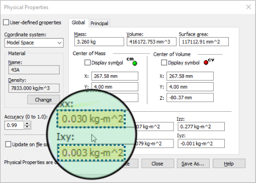
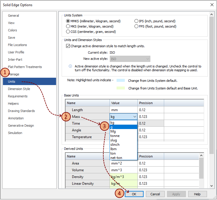
The Tip: The inertia units are derived from the base units of the document.
-
- Go to Solid Edge Options.
-
- Take the Units tab on the left.
-
- Under Base units, change mass to gram.
-
- Click OK.
Contributor: @Ulf_Eriksson
2. I am trying to use a simple point to constrain parts in assembly using the Axial Align relationship.
However, I notice that Solid Edge draws the point as a very small dot and I’d prefer having a cross instead.
Is there a way to change the appearance of the dot or simply an alternative to using a point?
The Tip: Solid Edge does not seem to support changing the thickness or the color of sketch geometry.
Hence my suggestion would be to consider inserting a coordinate system instead of a point.
A coordinate system is not only clearly visible but will also give you control of all six axes – an added bonus!
Contributor: @bshand
3. I’ve added some dimensions using the coordinate dimension tool. But now I want to add another dimension to that set, without having to create a new origin. How can I do this?
The Tip: Nothing simpler than that.
Just start the Dimension Coordinate command and click on one of the dimensions from the existing set.
After selecting it, you can place new dimensions connected to your current ones.
This video shows the steps:
Contributor: @Sander-NL
Video: @Tushar
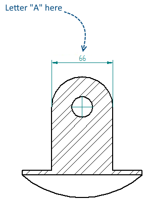
4. I would like to display a letter in place of a dimension value.
For example in the picture below I would like to see an “A” instead of the number 66.
Is this even possible and how to do so?
The Tip: This is really easy.
Select the dimension, then on the command bar, select the dimension type to ‘blank’.
Then in the ‘prefix/suffix’ box type in your desired character.
Done!
Watch this quick video that shows the steps:
Contributor: @SeanCresswell
Video: @Tushar
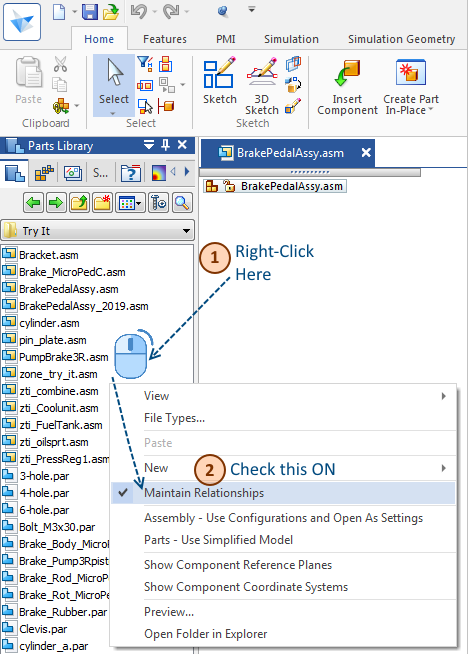
5. After I drag a part from our Parts Library and going through the entire Assemble process applying relationships I click back on the part only to find that the part is grounded. What’s going wrong here?
The Tip: It seems that you have turned OFF the Maintain Relationship in the library pane.
Turn it ON again and everything will be ok.
To do this, Right mouse button RMB click in your Parts Library pane in the white space and make sure Maintain Relationships is Checked. If originally unchecked, it will allow using relationships to position the part but then place a ground on the part instead.
Contributors: @KennyG and @hawcad
Tips compilation by:
Tushar Suradkar
Join the Solid Edge User Group on Facebook:


Comments