ST6: Synchronous Patterns
A couple of years ago in a different life I wrote a blog article about patterns in Solid Edge (ST4, I think). It was brutal. Sketching as a part of the pattern baffled me.
Now in ST6 they have revisited patterns, and I want to have a look at the new Synchronous patterns. ST6 Ordered patterns still retain the sketch method of doing things.
Rectangular Pattern
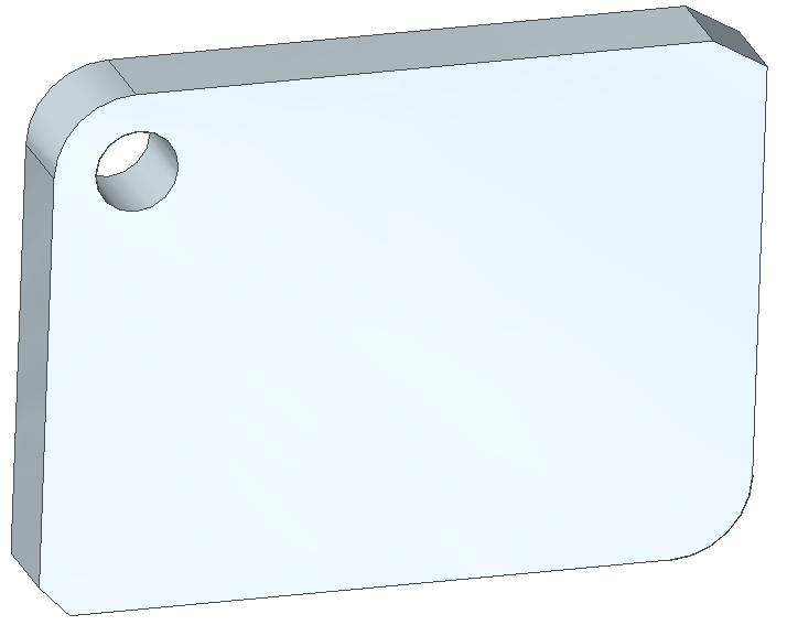
I started my pattern with this part that had an existing hole, and two chamfers – one with a 45 deg angle and another with a 60 deg angle. It also had two corners with rounds on them.
To start the feature, of course you need to be in Synchronous mode, and then select the face(s) of the feature you want to pattern. In this case it was just a single face on the inside of the hole. This lights up the icons on the Pattern group in the ribbon. Just click on the Rectangular Pattern icon.
As soon as you bring the cursor back over the part, you see the orange rectangle. This works like a sketch, but it’s not a sketch. The first corner is automatically placed in the center of your selected feature, and you are prompted to either place the diagonal corner of the rectangle to define the rectangular pattern or do one of several things to reorient the rectangle off of the default alignment.
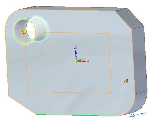 To just place the diagonal corner, just click. You can click anywhere on the face of part, or on an arc edge to place the point at the center of the arc. An icon will appear on the cursor when it is referencing the arc center.
You can also press N or B on the keyboard (for next or back), and the rectangle will automatically align with non-orthogonal model edges, such as the chamfer edges shown.
Or if you have clicked to place the diagonal point already, you can drag the ball on the end of the steering wheel to angle the entire pattern.
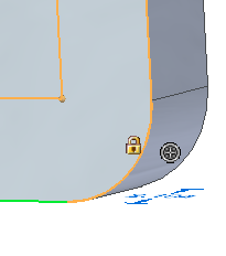 Pressing C on the keyboard will center the pattern about the original feature. You can pick up a lot of these tips by just watching the Prompt Bar on your screen.
You can change the pattern from a 4 x 4 pattern to a 3 x 2 pattern, with the pattern spreading out evenly over the area defined by the rectangle. Or you can change it from a Fit (fit in the rectangle) to a Fixed (fixed spacing distance) pattern using the Command Bar.
You can also use the Command Bar to suppress pattern instances (by clicking on red dots), or change the reference point for the pattern.
And of course you have to remember that patterns in Synchronous are procedural features, which means that they are driven by numbers, not just geometry, and they can be edited as a 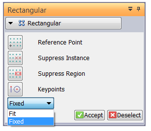 feature. Feature intelligence without history.
Circular Pattern
The ST6 Synchronous Circular Pattern has roughly the same workflow as the rectangular pattern. One thing I found to be aware of is that when placing the center for the circular pattern (or the diagonal point for the rectangular pattern), if you click on or near the origin, make sure that the plane is locked, because you might accidentally select another plane to put the pattern on.
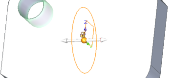
You can see above that the pattern is about to lock onto the ZY plane, but the selected hole is on the 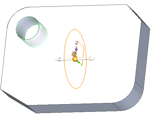 ZX plane. Pressing F3, just like in a sketch, will lock the pattern plane to the one where the pattern circle is currently displayed.
Use the Command Bar to toggle between arc and circle based patterns, as well as the other options available with the rectangular patterns.
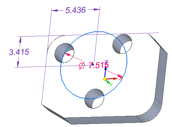
There is one gotcha with the circular pattern. If you want the center of the pattern to be defined by something other than the center of a circular edge or a part origin, you have to complete the feature, then right click on the feature in the Pathfinder, select Show Feature Origin, and then you can dimension to the center of the pattern from other features in the part.
 Summary
While the old Ordered patterns are still the way they were, the old guard still using primarily Ordered might not even notice that they were passed over this time. The new users using Synch have a lot to look forward to with ST6 Synch patterns. Nicely done, Solid Edge!


Comments