Multi-Bodies, Part 2: Managing and Manipulating

In the last post we talked about what kinds of things multi-body modeling (MBM) might be good for, on the conceptual level. In this post I want to talk more about some MBM facts – capabilities and tools.
Concepts
The concepts involved in MBM can be difficult to grasp at first, especially if you have never used them before. But they aren’t really all that difficult once you’ve seen them in practice.This blog series is not yet to the practical application stage, but we are getting there. There is a lot of ground-work to be laid first.
Let me just list out some facts that you need to know to work with bodies in Solid Edge (especially if you are coming to Edge from another modeler):
- “bodies” are always solid
- A “body” in SE can contain multiple volumes called “disjoint regions” (this is going to be confusing to SW users, since in SW, each volume is a separate body)
- Bodies can be active or inactive – features are only added to active bodies – an active body has a special Pathfinder icon and is opaque, inactive is transparent
- Bodies are either construction bodies or design bodies – the only differences are that construction bodies are not considered in drawings or mass properties
- Sheet metal bodies and regular part bodies can be combined inside sheet metal part files, and vice versa (this essentially does away with the requirement for special file type for sheet metal)
- “sheet” (and possibly “construction”) refers to surfaces, and are not treated the same as solid bodies (there is no collector in the Pathfinder for sheets/constructions)
- There is a concept called Active Assembly Body – when an assembly feature is added to a part, the Active Assembly Body is the body within each part that will be affected by the assembly feature.
 Features
The features that directly relate to MBM in Solid Edge are:
- Multi-body Publish – separates several bodies into separate parts
- Emboss – embosses one body with another body
- Insert Part Copy – inserts one part into another as a body
- Add Body – tells the software to add new features to a new (empty) body
- Union/Subtract/Intersect – common boolean functions
- Split – divides one body into multiples using a tool body
One of the tools that SolidWorks users will find

most odd is the Add Body command. SolidWorks just automatically adds bodies when any disjoint region is created. The Add Body function in Edge is necessary because bodies can consist of multiple regions, so the software will not automatically know if you want the new feature to be part of an  existing body or the first region of a new body. The organization of solid volume regions into bodies is entirely up to the user. For example, you might be planning to join two regions together into a single volume within a body. Or you might want a single cut to affect multiple regions. The only way to do that is if the regions belong to the same body. Remember that features cannot affect multiple bodies, but at the same time, bodies are what you say they are. So a cut or round can affect multiple regions.
Another thing to point out here is that ‘Works has four tools that do essentially the same thing as the Multi-Body Publish and the Insert Part Copy. It was always apparent to me that not a lot of thought went into these features in ‘Works because they were all almost duplicates, and the differences were subtle, and required a lot of investigation to differentiate. Solid Edge has condensed the functionality into two features, one to push bodies out and one to pull bodies in. The features in Solid Edge have been much more carefully considered, in my opinion.
Regions vs Bodies
In SolidWorks, some features such as Fillet and Shell cannot affect multiple bodies, but in Solid Edge, the Round and Thin Wall features can be applied to multiple regions, so this is a way that you can use the SE concepts of bodies/regions to achieve things that can’t be done in ‘Works. For this reason, it appears to me that working with regions is of more advantage than working with bodies. I would recommend using bodies only when you need to distinguish between a construction solid, which is used as a tool for a feature like Emboss or one of the Boolean operations (union, intersection, difference).
The downside of organizing all regions as a single body is that you would not be able to move one region independent of the other regions within a body. Also operations such as color don’t get as granular in their selection options to allow for selection of regions, although they do allow for selection of bodies. Of course all of this could just as easily turn out to be advantages rather than disadvantages.
Pathfinder
 There are also some really cool features for Pathfinder management, such as Show Body Features, which highlights in green text the features in the Pathfinder that touch the selected body. Nicely done. Also, I don’t know if anyone noticed, but the documentation crew did a nice job with a big PDF tutorial on multi-body modeling.
MBM is really only in its second release here in ST6, so the tools and the users understanding of the methods are in the early stages of development. As time goes by, and more users spend more time with these tools, the user community will develop more and more sophisticated methods based on the existing capabilities.

In the Pathfinder, you have collectors (folders) for Design Bodies and Construction Bodies. These collectors don’t
appear until you have bodies to go in them. Remember that  just because it looks like multiple bodies, it might just be multiple regions, so the collectors might not show up. You can move a body from Design to Construction just by right clicking on it and selecting the Toggle Design/Construction command.
Active bodies are opaque, and inactive are transparent. Design bodies by default are gray, and construction bodies are blue/purple. You can only have one active body at a time, and it doesn’t matter if its design or construction. (You can add features to construction bodies, which I hear is an enhancement over previous SE functionality).
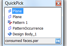
Notice also that when you pick stuff, the Body shows up as something that can be selected. When I took this screen shot, I got a Quick Pick that could have meant two different planar faces, a pattern feature, a pattern  occurrance, or a design body. You get to Quick Pick by hovering over a feature for a few seconds, then right clicking. This is similar to Select Other in ‘Works. You have to be careful if you intend to right click to get an RMB (right mouse button) menu, if you hover too long, you’ll get Quick Pick instead of the RMB menu.
Notice that there is no method to select disjoint regions. At this time, you cannot select a disjoint region except by selecting all the faces or features that make it. I would like the ability to select disjoint regions just for the sake of completeness. You might even show the disjoint regions in the body collectors for the same reason.
Summary
And then we haven’t even talked about surface bodies yet, which Solid Edge refers to as “constructions”. One thing I would like to see is a collector for these “constructions”. I find the ability to change the display of surface bodies of great value. In Solid Edge today you can change surface visibility by using the checkbox in the Pathfinder, but another collector with the surface bodies might be even more useful.
Thank you for hanging in there with me up to this point. Congratulations to anyone who has actually read this far! I know this discussion might sound academic and detached from daily modeling experience, but the subtleties of how these features work become very important when you are trying to create complex modeling methods. I apologize for overly comparing the new (in ST5) functionality to ‘Works, but that is my point of reference as I work my way through Solid Edge teaching myself the tools as I go along.


Comments