Step Draft
Every now and then, I pick a topic that needs a little research and blog about it. Yes, maybe it’s a little obscure, but maybe it’s something you didn’t know about before and now you do. This topic came up on the forum, and I wanted to look into the issue, and thought more people than just the guy asking the question might benefit from the answer.
I’m using Ordered features for this example. And I’m using my own simplified part. The original question on the forum had a part with some detail, but demonstrating the tool on that part would have involved a lot more than just what he was asking. I would have had to rework several features (just like he will have to do when he has to do this himself), but the message of Step Draft would get lost in there.
So.
Step Draft. Some people call it Pivot Draft. It’s generally a practice used in plastic parts when you have to create draft (angled faces) from a non-planar parting line – usually one with straight line steps. Some people tend to use this only on blow or roto molded parts, but I’ve also seen it on injection molded parts.
Sometimes the parting line on a molded part has to move from the plane where it is easy to create the parting line to another location, maybe because there is an 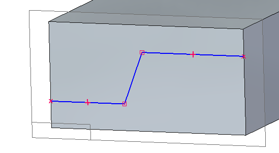 undercut for an assembly snap. You wind up with a “Z” shaped edge across the part, where faces on one side of the Z have to draft in a different direction from the faces on the other side of the Z.
If you were to sketch it, it would look like this.
 There is a function in Solid Edge that helps you deal with this situation. Draft is the
 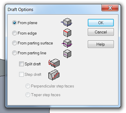 tool for creating normal draft in Solid Edge, but it has some advanced options that might not be as widely used. If you click the Options button in the Draft CommandBar, you’ll get these options shown to the right. The one I’m interested in here is the from parting line option, and the step draft box below that.
If you have used other software, be aware that Solid Edge does not work like those other CAD tools. That’s not good or bad, it’s just different. In the other CAD tools you need to draft from edges, but here in Solid Edge, we draft from projected curves. Avoid the 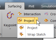 temptation to split faces. Use that sketch shown above to Project onto the face where you want to apply the draft. Once the sketch is in place, go to the Surfacing tab, the Curves group, and select the
 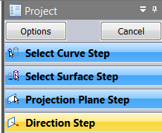 Project tool. Work through the steps to project the sketch onto the face. Remember to follow the prompts on the PromptBar. Even if you’re an experienced user, if you’re working through a function you’re not that familiar with, the PromptBar will tell you what Solid Edge is expecting from you next.
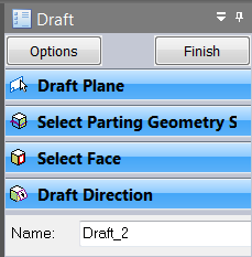 From here, the workflow for the Draft feature takes over.
The draft plane can be defined during the feature or before it. Just be aware that if you want to do it during the feature, and for some reason you fail to create the draft feature, the plane is not created either. The draft plane should be located between the high and low points of the stepped parting line. It can be anywhere in between or at the extremes. If you want to minimize the “shelf” of the step, then put the plane inbetween as shown below.
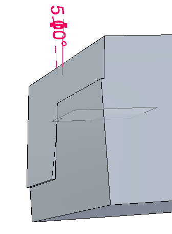
Here you can see the draft plane is in the middle of the step, and there is a small shelf at the top and bottom.
This might be a good place to talk about the reason for creating this draft in the first place. If you did not create the small shelf, the “L” shaped face would be broken up into 3 separate facets. Because the draft from the angled part of the parting line would break up the top edge the the part, this is sometimes undesireable for either cosmetic or molding purposes. Stepped parting lines are more expensive to design, and more expensive to create tooling for, as well as asthetically questionable. Generally, avoid it if you can.
Below is an image of what happens when you have stepped parting line, but can’t deal with the “shelf”.
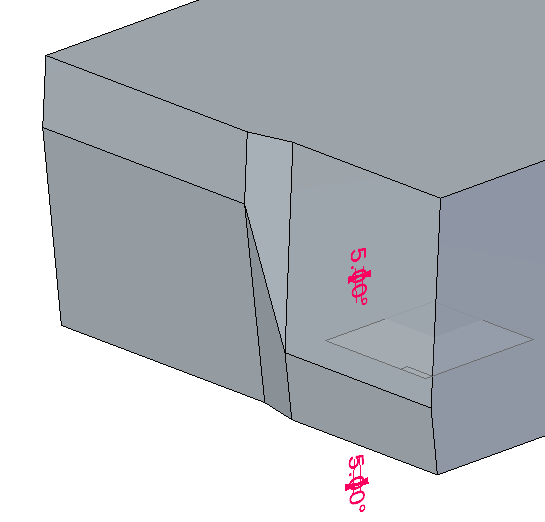
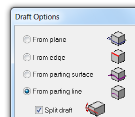 This (above) is what happens when you use the Split Draft option. In this case, it doesn’t matter where the draft plane is located, it just assigns a direction. In the Step draft option, it also assigns where the draft starts.
In both of these situations, I used 5 degrees of draft, which is usually more than you have to use. I use that value here to exaggerate the effect and make it more obvious what’s going on.
Just a note about the Split Draft. In Solid Edge, you can create the draft on both sides of the parting line, while in some of the other software that you may have used out there, you can only get the draft on one side at a time, and have to create a second Draft feature in order to get draft on the second side.
The part I used as an example has both types of draft on it (step and split), and is attached at the bottom of this article.


Comments