Helical Features
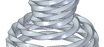
 Machine design has long been Solid Edge’s strength. Machine design is usually about parts with square corners and flat sides. Sheet metal part, machined plate parts, and turned components along with off the shelf parts.
But sometimes, even with standard machine parts, the geometry gets more complex. One of those situations is what I want to write about today – Helical Features.
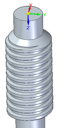
Helical Features can include things like threads, gears, springs, auger/mixer blades, cutter tools/drills, coiled cooling tube, and other things CAD users might have to create from time to time such as coiled wire, propellers, architectural spiral staircases, and so on.
Solid Edge has three main tools to create helical features in both Synchronous and Ordered:
- Helical Protrusion
- Helical Cutout
- Sweep (with Twist option)
Let’s discuss each of these features in some depth: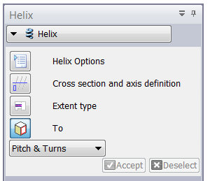
Helical Protrusion/Cutout
The Helical Protrusion is also referred to by the interface as simply “Helix”. It seems to make more sense as an Ordered feature rather than a Synchronous feature. Some of the options such as the orientation of the cross section do not work in Synchronous mode.
The workflow for the helical protrusion and helical cutout is:
For Synch:
- Create sketch with profile and axis
- Start Helical Protrusion feature
- Select profile and axis
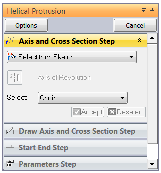
- Right click to accept
- Click Helix Options to adjust parameters
For Ordered:
- Create sketch with profile and axis
- Start Helical Protrusion feature
- Select profile and accept
- Select helix axis line (no accept)
- Select one end of the axis to tell Solid Edge where to start
- Set the helix parameters
- Establish the end condition
It seems that in ST6, you have to pre-select a thread profile if it has more than one side (if it is say a rectangle rather than a circle).
Sweep with Twist Option
In order to turn on the Twist option, you have to have a path and a profile already selected. This feature can cause a large Options dialog to open as soon as you start the feature, and the Twist option is grayed out. This c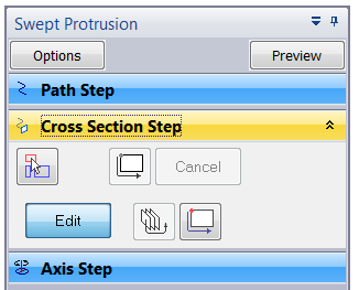 an be kind of discouraging if you don’t know what you have to do to turn it on.
The good news here is to just follow the steps in the prompt bar. Select the Path then accept. Select the cross section, then accept. Once both the path and section are selected, you can go back to the options and turn on the Twist.
Another nice thing about this feature is that if you create this as an ordered feature, the path can be converted into a spline curve using the Convert to Curve tool. This can turn a straight helix into a curvy helix.
Finishing Threads
One common question among people who create threads in 3D CAD is how you finish off the threads nicely. There are a couple of methods I use. 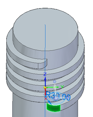 One is to open a sketch on the square end of the thread, add a centerline toward the inside of the part, and revolve the thread shape. This only works if the cross section of the thread is perpendicular to the helix, which is not the case in these parts.
A second way is to just put a big fillet on the edge of the thread. This is the method shown to the right.
A third way is more complicated with creating another profile inside the part and lofting from the square end into the part.
No Helix Curve Feature
It might seem odd, but with all of these helical features, Solid Edge does not have a Helical Curve feature. The helix is built into the features listed above, and you never actually see any type of helical curve. If you have to make a part with helical features that don’t fit into the pre-established features listed above, you might be in need of a workaround. For example, a marine propeller has helical features, but does not fit the helical features neatly. Here are some workarounds to create helical curves:
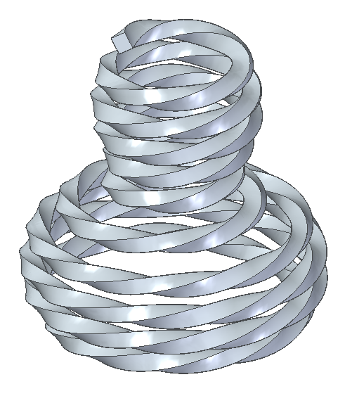
- Draw two perpendicular lines, and sweep one along the other to create a surface, using the Twist option. You can use the outer edge of the surface as the curve. Trim the corkscrew surface with a cone to create a tapered helix, or with a revolved shape to create a variable diameter helix.
- Create a cylindrical surface, a plane tangent to the surface, and an angled line on the plane. Then use the Wrap curve to wrap the line onto the surface. This allows you to control the helix angle and the developed length of the helix.
- Use keypoints to build a helix. This is probably more difficult and less accurate than the other methods, but if the keypoints are already available
Summary
When you understand the tools you can achieve results that you might not have imagined.Sometimes it just takes a little exploring and the willingness to be not exactly sure what you’re doing. This becomes more difficult the more specific results you’re trying to obtain. It always amazes me that tools created by someone who probably never imagined the range of things that would be done with the software.


Comments