Speeding design of plastic parts
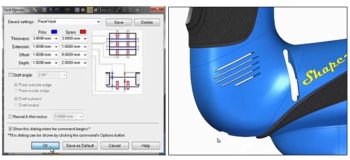
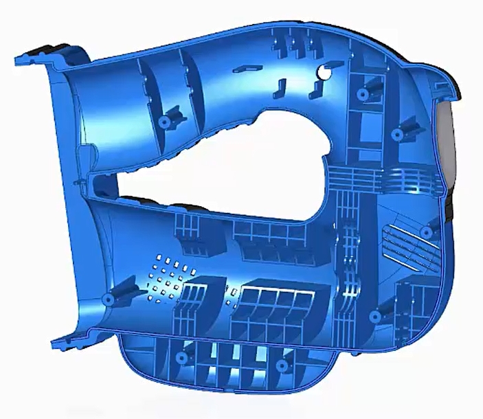 Solid Edge has specific commands for rapidly creating the features commonly used in plastic parts
Solid Edge includes excellent capabilities for designing plastic parts, and this is the focus of the 14th webinar in our Solid Edge Digital Transformation webinar series. You can watch the webinar replay to see for yourself how these capabilities significantly reduce the time spent to create features like webs, vents, lips and bosses that are commonly used in plastic parts, freeing you up to focus on the overall functionality and aesthetics of your product.
The demonstration starts around 5 minutes into the replay where Doug Stainbrook shows how the Solid Edge Assembly environment can be used to design the plastic housing for a jigsaw, and fit this around internal components. Geometry from these components can be used in the creation of the housing using offsets to ensure that clearance exists where needed.
The next area of focus is the ability to analyse a plastic part for moldability, especially if there are any overhangs or vertical faces that would make it difficult to extract the part from the mold. The Draft Analysis command in the Inspection ribbon is used to highlight any areas of the part that could contribute to this problem. In this case some vertical faces are found and these are highlighted in green. A draft angle of 3 degrees is added to each of these surfaces to ensure the part can be extracted easily from the mold tool.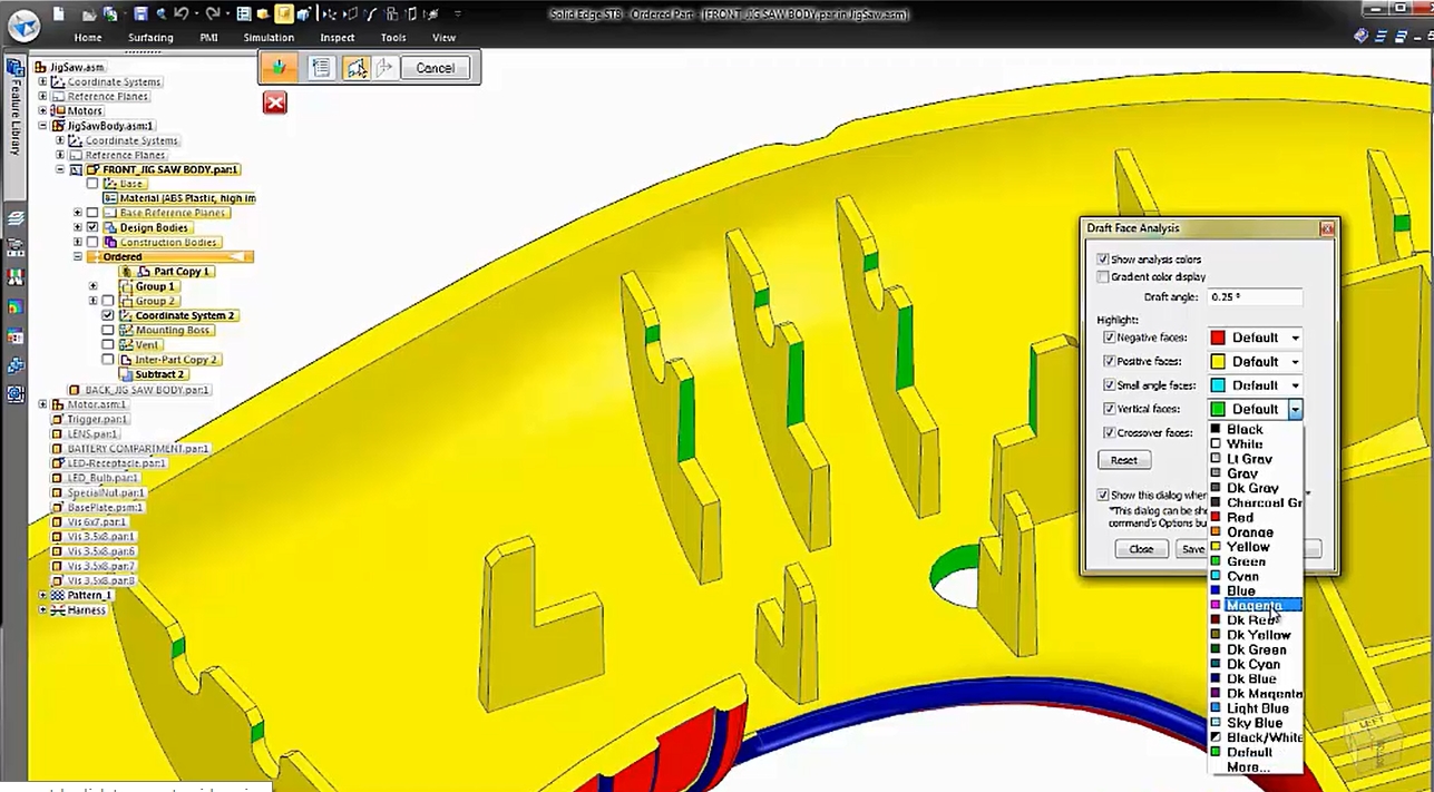 The Draft Face Analysis command is used to detect potential problems with molding the part. Here, vertical surfaces are highlighted in green. A draft angle can be added to these surfaces to solve this potential problem.
Networks of webs are often used in plastic parts to strengthen the overall design or to support internal components, and the Web Network command in Solid Edge makes it very easy to create these features. In the demonstration a simple sketch is created to define the location and parameters of the desired web network. The desired thickness of the webs is specified and a draft angle added to the faces of the web. The web network is quickly created and mirrored to the other side of our housing. In addition to strengthening our housing the web network is also used to locate and support a motor. The motor is displayed in the assembly and its geometry is used to remove parts of the web network to correctly position and support the motor.
Mounting bosses are a common feature of plastic molded parts, they may be used to locate internal components like a PCB or they can be used to interlock two halves of a plastic assembly. In the demonstration the Mounting Boss command is used to quickly specify the exact parameters for the boss we want including its dimensions, the number of supporting ribs required and the draft angle to be placed on the surfaces. We also create a pattern of these mounting bosses around the housing with the locations driven by data from an Excel spreadsheet.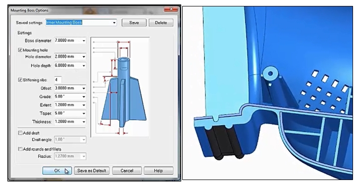 Mounting bosses can be quickly added to plastic parts. The dimensions, draft angle and number of ribs are easily specified using this dialog.
Interlocking plastic parts often use a lip on one part and a groove on the other part to locate the parts correctly and form a seal between the two halves. In this demonstration we quickly place a lip and a groove on the two halves of our jigsaw housing. Finally we need to add a vent to ensure that air can flow around the motor for cooling. Again Solid Edge has a specific command for this, we just need to create a sketch that defines the boundary of the vent and in the dialog we define the number and size of the ribs and/or spars that we want. 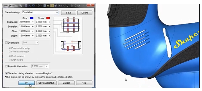 Adding vents to plastic parts is a common requirement to enable cooling of motors and other electrical components
A short case study is then presented on one of the many Solid Edge customers who are using these capabilities to rapidly design plastic parts. This webinar in just one in a series of 15 webinars covering a wide variety of topics, register here to watch the replay of the plastic parts webinar and you will get access to all 15 webinar replays!


Comments