Tips and Tricks from Forum Users #24
No new videos in this installment, here’s an assortment of short tips and tricks based on the discussions in the Solid Edge forum.
Due credit is given to respective contributors.
And a quick list of the previous compilations:
T&T #01, T&T #02, T&T #03, T&T #04, T&T #05
T&T #06, T&T #07, T&T #08, T&T #09, T&T #10
T&T #11, T&T #12, T&T #13, T&T #14, T&T #15
T&T #16, T&T #17, T&T #18, T&T #19, T&T #20
1. Is there a way to display an information window in Solid Edge about a selected object like a face or edge similar to Ctrl + I in NX?
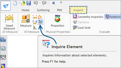
The Tip: Sure. There is an ‘Inquire Element’ command on the Inspect ribbon that will provide information about a selected element.
If desired you can set up a keyboard shortcut for it.
Here’s a video on the Solid Edge YouTube channel that shows the steps for assigning a keyboard shortcut to a command:
Contributor: @KennyG
2. In the Part Copy command, I have mistakenly saved the setting for not to update links and never prompt. How do I access the list of settings to change it back to either notify or automatic update?
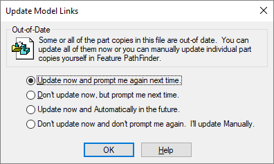
The Tip: That’s easy.
- Right click on the part copy in the Pathfinder and select Edit definition from the context menu.
- Click the Parameters Step on the command bar.
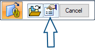
Click on the little link symbol at the top of that dialog.

Contributor: @bshand
3. I have a part file with curves and would like to use it in an assembly to create a weldment using the curves/sketches from the part but when I put the part into the assembly, the curves and sketches are gone. Any ideas?
The Tip: Not an issue. Just right click on the part in the Pathfinder and go into the Show/Hide Component command and turn On the Sketch and Curve options and they will show up in the assembly.
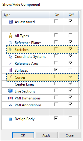
![]() Note: If you right click in an empty space in the assembly and choose the same command, the curves and sketches for ‘all’ parts in the assembly will be displayed.
Note: If you right click in an empty space in the assembly and choose the same command, the curves and sketches for ‘all’ parts in the assembly will be displayed.
Contributor: @uk_dave
4. I have a model imported into the Synchronous environment in Solid Edge and have recognized the holes. Easy so far.
When I select one of the holes to change its type from simple to a counterbore, all I see is the hole size callout and there is no option on the command bar related to the hole.
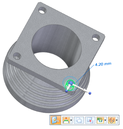
Is it possible to change the hole-type as well on imported models using the synchronous commands? If yes, how?
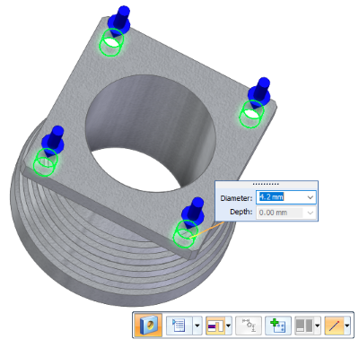
The Tip: Absolutely! And this is really easy, once you know the process of course……select one of the holes [graphically, or in Pathfinder] and then select the PMI based title [normally the primary dimension for hole] this will then show the familiar “Hole Options” in the command bar, to change from simple to counterbore. Done!
Contributor: @SeanCresswell
5. How do you change the toolbar and ribbon bar color in Solid Edge? Thanks for any help.
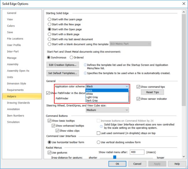
The Tip: You can change it on the ‘Helpers’ tab on the Solid Edge Options dialog
Contributor: @GregLuckett
6. Are there any settings while inserting the base view in drafting where if I select New -> Create Draft from the active model and the first view comes in as Isometric, but I want to it insert a Top View or a Front View? Is this even possible?
The Tip: When placing a view with Drawing View Wizard, you can change the settings and then save those settings. If for instance you always want a Top view when placing your assemblies, you would select the top view while using the Wizard and then use the Saved Settings button to save that. Using that saved setting will always place the top view now.
To make it automatic, open your Solid Edge Options while in a DFT file and go to the Drawing View Wizard page. In the middle of the page is an Assembly Drawing Views section and one of the lines in it is the “Saved Settings” organized by Small, Medium, Large assembly occurrence counts.
Set the Saved Setting field to the saved setting you created for the size of assembly needed or set them all for any assembly size and Apply.
Now when placing assembly Drawing Views you will have the Top view shown automatically.
Contributor: @KennyG
7. When I open STP files containing assemblies they always open as one part or body in the Solid Edge assembly environment even when I am choosing assembly templates when prompted, but it still does not extract the individual parts.
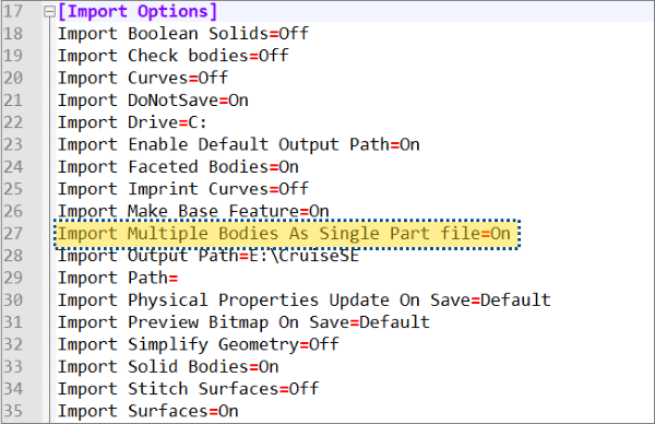
The Tip: Your STEP translator settings are probably set to import as a single body part. Turn that Off.
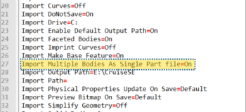
The STEP.ini file can be found in the Program FilesSolid Edge xxPreferencesTranslators folder and opened in any text editor for example Notepad or Notepad++ as seen in the image below. And the setting is typically near line #27.
Contributor: @bshand
8. I know it is possible to right click on the top of the Pathfinder and collapse it, but if the Pathfinder is too long, it’s a hassle to scroll all the way up. Is there a shortcut to collapse the pathfinder?
The Tip: There is no easy way to do this, such as adding it to the QAT…..another way is to double click [any of] the stack header[s] to toggle between expanding & collapse. The problem is, as you say when the Pathfinder is very long, the main stack header is part of the scrolling bundle.
The best way to combat this condition would be to make use of pathfinder groups, such as seen in this video.
Contributor: @SeanCresswell
Video by: @Alan


Comments