Translating Solid Edge Files from the Command Line

In this recent Solid Edge Community forum post, there was discussion and mention of a Solid Edge command line translation capability. In this article we review this little known Solid Edge command line translator tool and its options available.
Under “C:Program FilesSolid Edge ST8Program” exists the file “SolidEdgeTranslationServices.exe”:
This is a command line tool that was originally designed as a utility for translating Solid Edge files to third party file formats for use with PLM systems [Teamcenter cough, cough ![]() ]However, there is nothing preventing us from using this utility outside of PLM
]However, there is nothing preventing us from using this utility outside of PLM ![]() Unfortunately, given the intent of the tool, there is no readily available documentation on this tool in the Solid Edge help system:
Unfortunately, given the intent of the tool, there is no readily available documentation on this tool in the Solid Edge help system:
If you attempt to run the tool from the command line without any options you will receive an error and no prompting of arguments is provided. If you attempt to run the tool with typical help arguments, again you will receive no prompting or help on what arguments are needed or available:
Thankfully those helpful folks at GTAC ![]() have already documented the command line options for you:
have already documented the command line options for you:
So for those who don’t access the GTAC online resources (why aren’t you?), what are the arguments available for SolidEdgeTranslationServices.exe?
Here are the command line switches available for SolidEdgeTranslationServices.exe:
- –i = input file
- –o = output file
- –t = what format to convert to (e.g. pdf, tif, dwg, jt, bmp, igs, etc.)
- –w = width
- –h = height
- –r = resolution (100, 200, 300, 600, 1200)
- –c = colour depth (1, 8, 24 where 1=MONOCHROME, 8=256 COLORS, 24=TRUE COLOR)
- –v = visibility of Solid Edge (TRUE, FALSE)
- –q = image quality (LOW, MEDIUM, HIGH)
- –m = multiple sheets (TRUE, FALSE)
So how to actually use the command line translator? At a minimum you must supply the input file, “-i”, output file, “-o”, and the type of file to convert to, “-t” e.g.
SolidEdgeTranslationServices.exe -i=”C:Program FilesSolid Edge ST8Trainingstddb3d.dft” -o=C:Temptest.pdf -t=pdf
NOTE: if your file path names contain spaces you will need to surround the paths with quotes ” “.
Voilà, a converted PDF from the Solid Edge draft — all from the command line:
So what file types for the -t parameter can SolidEdgeTranslationServices.exe actually convert to?
Here is the list of supported conversion formats and the file type to specify for the “-t” parameter:
Solid Edge 2D Draft File Types
- Adobe Acrobat (pdf)
- AutoCAD (dwg)
- AutoCAD (dxf)
- JPEG Image (jpg)
- IGES (igs)
- MicroStation (dgn)
- TIFF Image (tif)
- Windows Bitmap (bmp)
- Windows Enhanced Metafile (emf)
Solid Edge 3D Model File Types
- ACIS (sat)
- Adobe Acrobat [2D & 3D] (pdf)
- CATIA V4 (model)
- IGES (igs)
- JPEG (jpg)
- JT (jt)
- Parasolid (x_t)
- STEP (.stp)
- STL (stl)
- TIFF Image (tif)
- VRML (wrl)
- Windows Bitmap (bmp)
- XGL (xgl)
- XML (plmxml)
As you can see, there is quite an extensive list of file formats supported by the Solid Edge command line translator.
So what do all of the command line options do? Obviously not all command line options would be appropriate for all file types. For example, you would not specify a width or height for a STEP file. To be honest there are too many different file types and options appropriate for each of the file types to even begin to individually and fully document them all here.
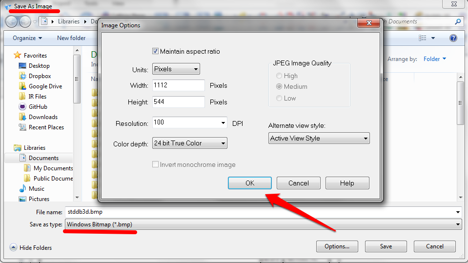
If you are not sure what options would be appropriate for your desired file translation, simply open up Solid Edge, manually create a file translation, and pay attention to the options available to you when manually creating the translation from within Solid Edge:
So in the above example we are reviewing the Save As Image to Windows Bitmap options available. From this screenshot, when compared to the command line line options available, we can easily deduce that the following would be appropriate options for the command line, as each option is selectable and settable within Solid Edge:
- –w = width
- –h = height
- –r = resolution (100, 200, 300, 600, 1200)
- –c = colour depth (1, 8, 24 where 1=MONOCHROME, 8=256 COLORS, 24=TRUE COLOR)
However, the option “JPEG Image Quality” is not selectable for a Windows Bitmap so the following command line option would *not* be appropriate:
- –q = image quality (LOW, MEDIUM, HIGH)
NOTE: In order to generate 3D PDF files with this utility you must first enable 3D PDF in the “C:Program FilesSolid Edge ST8ProgramDefine_SolidEdge_Properties_ForWorkflow_ToSync.ini” file by editing the file and setting “Export 3D PDF from part or Assembly=1”. If this option does not exist in the file, then you can manually edit and add the option at the end of the file. Without this setting existing or being set equal to 1, PDF files generated from Solid Edge models will be 2D PDFs:
So, now that you know there is a Solid Edge command line translator available, what can you do with such knowledge? Well, you could create a Windows scheduled task to automate the conversion of your Solid Edge draft files to PDF files overnight. Or you could create a utility to allow conversion of Solid Edge files directly from within Windows Explorer. Or…
Happy translating 🙂


Comments