Understand the Solution Manager
 The Solution Manager helps you sort out which relationships are causing a particular edit to not work as expected. It also helps you visualize different solutions to the problem by analyzing the error chain.
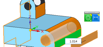
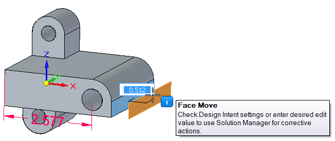
If I select the end face of the model, as shown, and drag the Steering Wheel arrow out from the model, this edit fails for reasons we are about to research.
 Finding out why things happen is an important way to understanding how things work and what you should reasonably be able to expect your tools to do. A few extra minutes spent researching problems from time to time will build your skills and knowledge of the software significantly.
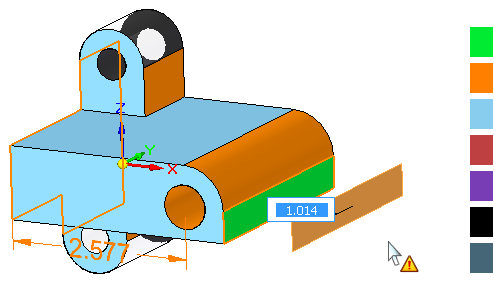
When I click to place the face about an inch from the original, the model faces turn colors.
The colors, from top to bottom of the legend shown above right, are:
Transparent = doesn’t take part in solution
Green = selected
Orange = error chain
Blue = solves correctly
Red = isolated (selected rules turned off)
Purple = rigid set
Black = grounded
Slate = rules totally off
The colors that you are concerned about here are the orange faces. History-based users can think of all the orange faces being overconstrained. Orange is the “error chain” color. Think of a chain that is preventing your edit from happening. Each dimension, face relation, or Design Intent assumption is a link in that chain, and you have to decide which link to relax, or break in order to allow your edit to work.
The way to examine the links in the chain is with right mouse button clicks and hovering with your mouse. For example, I can see that the fillet face is part of the error chain because it is orange. Notice that the 2.577 dimension is orange, because it is also part of the problem.
 When you right click on the fillet face, the Solution Manager shows the set of relation icons to the right. The yellow triangle means that relation is part of the error chain, so the tangent between the fillet and the top flat face is not part of the problem.
This tells you that the fillet face has three Design Intent assumptions, and hovering your mouse over the icons will highlight the two faces involved in each relation. So hovering over the Concentric icon highlights the fillet face and the hole.
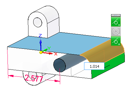 If you click on one of the icons, it will go gray and break that relation temporarily, and show what the model would look like with that relation broken. Clicking on the Concentric relation breaks the error chain, and shows what the model would look like without that relation.
To put the model back the way it was, click on the gray icon again to reactivate it and show the model in its error state again.
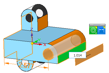 Next, I’ll click the right mouse button again to hide the icons, and then right click on the face of the hole. This shows the relations attached to that hole, and brings up the concentric icon as well as a dimension icon. If you click the dimension icon, that button goes gray, and the Solution Manager turns the locked 2.577 dimension to an unlocked (blue) dimension, meaning that the edit would drive the dimension. This solves the problem , but in such a way that the hole moves to match the fillet.
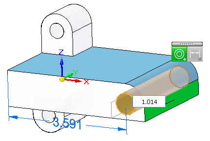 Accept this second result by clicking on the green checkmark in the Advanced Design Intent.
There are a few things here to remember, but with all of the symbols decoded and the ways to access the information spelled out, the Solution Manager is accessible. With the Solution Manager as a safety net, you can feel more secure in exploring more Synchronous Edits I think this also helps demonstrate that Synchronous really works backwards from the “fully constrained” concept. Nothing is going to move unless you allow it, which is the reverse of the basic history-based concept which is everything can move unless you constrain it.
Thanks to Chris Dayton in Planning for helping me with some of the ideas for how to explain this, and for the use of a model I borrowed from him.


Comments