Why Would You Use Virtual Components? Part 2

I’ve re-written this article 3 or 4 times as my understanding of Virtual Components (VC) has evolved. If you really want to understand this functionality, I recommend you do the tutorial starting on page 3-2 of this PDF document which is part of the Solid Edge Help.
There are three steps in the VC process:
- Place Holder– parts with no files and no geometry, they exist only in the assembly Pathfinder
- Source component – Assembly layout sketch geometry is moved into place holder parts
- Pre-defined components – placed in assembly using 2D sketch, but also contains 3D data
You can think of these as sequential steps with the end goal of making a library of pre-defined components that can be re-used easily in projects that use similar components arranged differently. OR, you could think of these as three distinct states, each usable on its own. I think that the intention behind VC was for the place holder – source – pre-defined process to be considered a sequential set of steps to build library parts. But with a little imagination, it’s not hard to come up with independent uses for each of these three states.
I’m gonna go out on a limb here and say that the ultimate goal of the VC process is to have a library of a bunch of pre-defined components that can be placed in layout sketches using 2D references (called component sketches), and then at some point “turn the lights on” and all the 2D turns into 3D.
 Let’s take this apart and look at the individual pieces – really three steps in a process – to understand the whole thing.
Place Holder
When you initially start a modeling project, you can lay out the scope of the work by creating a bill of materials in the Pathfinder. This is just text within the assembly file that represents the organizational structure of the Solid Edge model. (Notice that virtual part and virtual assembly icons in the figure to the right are slightly different from regular part and assembly Pathfinder icons.) This list might use names, descriptions, or numbers. The place holders do not yet have any geometry and are not yet associated with files outside of the assembly.
The place holders can represent parts or subassemblies. You can also mix real parts with these virtual components, as you can see with the last two entries in the first image. You can also have sheet metal virtual parts, but now (starting in ST6) that you can have sheet metal features in non-sheet metal parts, I assume this is less important than it once was (VC has been around since version 16 or 17).
Later in the process, you can publish these place holders into real assembly and part files, and then add geometry to the parts using the sketch data brought in from the assembly layout sketch.
This is something you might set up if you were the engineering manager, and needed to assign portions of a project to individuals. Once you have the organizational structure down like this, you can assign sub-systems or subassemblies to different people to work on.
I started researching this functionality assuming that Solid Edge Virtual Components would be approximately equivalent to SolidWorks Virtual Components. Let’s just say I was wrong. Works Virtual Components can have 3D geometry, but they only exist in the assembly, and they don’t have any of the following functionality. Works does have a function called Smart Component that is similar to the pre-defined component step in the VC process.
Source component
 Sometimes you start an assembly with a sketch, and then assign parts of the sketch to virtual components.
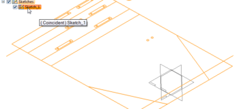
To add part of an assembly sketch to a virtual component, make sure you’re editing the sketch, right click on the VC and select Edit Definition, then select the portion of it you want to attach to the VC. The Prompt Bar should walk you through this. Then you should click to establish an origin and click again to establish an X direction, then select the plane the VC should go to (top, front or side).
Notice that the icons for VC with sketches (Top Plate) are slightly different than those without sketches. The Top Plate is a VC that contains a sketch. The Solid Edge Help documentation refers to a VC in this state as a “source part”.
Pre-defined components
In order for an existing part to be used as a virtual component, the part must have 3D geometry plus at least one sketch representing the part which will allow you to place it using mating 2D data in the assembly layout. The parts are used as if they were library parts, and the 2D is used to place/locate the part like a sketch block. The Solid Edge Help refers to VC parts in this state as “pre-defined” components.
If you were going to lay out machines on the shop floor, and you already had models of your machines, this is the method you would use. You would start an assembly, create a layout sketch of your shop floor area, use the virtual component tools to place 2D sketches from the library, and then later publish the virtual components to turn on the 3 D. (To the right is a graphic from the Help documentation showing the various icons used for Virtual Components.)
The Help also shows the basic workflow for virtual components as this:
• Define the virtual components you need.
• Add existing documents to the virtual assembly structure.
• Assign 2D geometry to individual virtual components.
• Position virtual components.
• Publish virtual components.
Positioning Virtual Components
A classic VC application would be positioning equipment in a factory layout. It would be like using blocks in AutoCAD or little cutout pictures of furniture as you try to layout your office.
===========================================================
Ok, I realize that’s all clear as mud. Let’s start over again and approach this differently.
 Virtual Components is a method you can use to locate pre-existing parts or sub-assemblies which contain special “component sketches” into an assembly which contains a layout sketch.
I think part of the reason that people get so confused about this topic is that all of the examples are circular – you start from an assembly, create the VC from that assembly, and then put those parts back into the original assembly. This workflow doesn’t make any sense, and you wouldn’t use it on a real project.
The examples shown in the Help are also trying to talk about making VC and placing VC as if they are part of one continuous process. But they aren’t, they are two separate processes. This is a very difficult topic to get your head around. I can’t imagine being one of the folks writing the initial Help documentation when no one had ever really used this stuff.

The Structural Editor interface is a beautiful thing on its own, and it can be used for totally unrelated purposes independent from the rest of the VC process. It is also used when building the assembly from pre-defined parts.
The Help examples should really start by showing how to create these special VC library components from existing solid models. This should include identifying connection points, adding the component images (2D drawing view visual) to represent the 3D part.
Next, the examples should show you using a 2D workflow to place the VC into an assembly layout sketch, and publish the parts with 2D view to 3D view.
Terminology
Part of what has been confusing for me is that some terms are used for multiple purposes. For example, “Publish” can mean taking the text BOM in the Pathfinder and making real external part and assembly files from it. “Publish” can also mean taking real parts and assemblies (pre-defined components) and changing them from 2D view to 3D view. These two actions are very different and might benefit from having different terms.
The term “Virtual Component” is also used in multiple ways. It is used to represent all three states in the process – place holders, source components, and pre-defined components. This I think adds to the confusion. To me, the “virtual” part of this process is the first step – the place holder.
I’m not sure where the “Zero-D” terminology comes from. You’ve clearly got the distinction between 2D and 3D. The place holder state might be considered 0D, becuase it’s just a name with zero geometry. That leaves us skipping over 1D, but then I guess naming schemes for CAD tools don’t really have to be totally rigorous.
What Is It?
The Virtual Component process may suffer from wanting to do too much at once. It’s hard to identify because it covers so much ground. Breaking it up might make it easier to understand.
The Place Holder idea I think should be called Virtual Components on its own. Changing virtual to real on a selective basis (and showing VC on draft parts lists) really opens up new frontiers.
The Source Component might be re-branded as a method to migrate assembly sketch data into parts, in which case the word “source” would be backwards, because the assembly would be the source and the component would be the target or recipient.
Pre-defined component I would rename to somehow include the word “Library”, which might help to explain what it does. Maybe “magnetic library component” because you snap it into place using the sketch entities.
Summary
So, if anyone is still reading, this is what you’ve come here to hear. Is this Virtual Component functionality worth your time? After talking to the guy who came up with this functionality, it seems clear that there is a lot more he wanted to do with it. I think there is a lot of potential that they weren’t able to implement the first time around. But let’s just talk about today.
If you have a design process that could use an assembly layout sketch, and you re-use the same parts frequently (like putting electronic components on a circuit board), VC is something you should investigate. I think it will accelerate this process, and give you a way to display the library parts with a lighter weight display.
If you need to structure large modeling projects without actually making parts and subassemblies, then the Structural Editor interface is something you should investigate. I really like the method of creating parts lists without external references or geometry, and editing the overall structure in that state, only publishing the parts list to CAD files once the structure is establishded.


