Tecnomatix 14 – What’s New?

Tecnomatix® software is designed to empower manufacturers to digitalize manufacturing and the process of transforming their innovative product ideas and raw materials into real products. The latest Tecnomatix release, including Process Designer 14, Process Simulate 14, RobotExpert 14 and Plant Simulation 14 continues to deliver advanced technology in the areas of planning, simulation and production.
In the latest release of the Tecnomatix portfolio, new capabilities deliver enhanced solutions for robotics programming and virtual commissioning, human factors and ergonomics, plant simulation and throughput optimization, and virtual reality, while helping to improve the overall user experience and management of the software.
We think you’ll be impressed with what Tecnomatix 14 continues to do for you! Please let us know what you think in the comments section below.
Tecnomatix benefits and features at a glance:
-
- New capabilities for robotics programming and virtual commissioning.
-
- New capabilities for human factors and ergonomics.
-
- New capabilities for plant simulation and throughput optimization.
-
- New capabilities for virtual reality.
Robotics programming and virtual commissioning.
Conveyor stacking
Conveyor functionality has been enhanced in several ways. You can now create more realistic simulations of stacked objects that show the effects of conveyor speed and simulation time interval. They can also enforce threshold values for skid contact. Also new in this version, Process Simulate Commissioning users can now use Conveyors in a way that accurately reflects actual conveyor behavior and reduces commissioning time for lines with conveying systems. By using the Lower and Upper Limit settings users can maintain a consistent distance between the parts or skids on the conveyor and prevent stacking of those in the rear when the lead part or skid stops moving.
Return to top. ^
Robot jog, cycle time reports, simulation monitor and panel
This release contains many new robot jog options, cycle time report enhancements, and simulation monitor and panel enhancements. For a complete list of updates, please see the release notes.
Return to top. ^
Swept volume performance
Swept Volume performance has been improved by more than 50% in this version and the algorithm is no longer dependent on the graphics card, which means that the functionality works well on machines with lower-end graphics cards as well as on virtual machines.
Return to top. ^
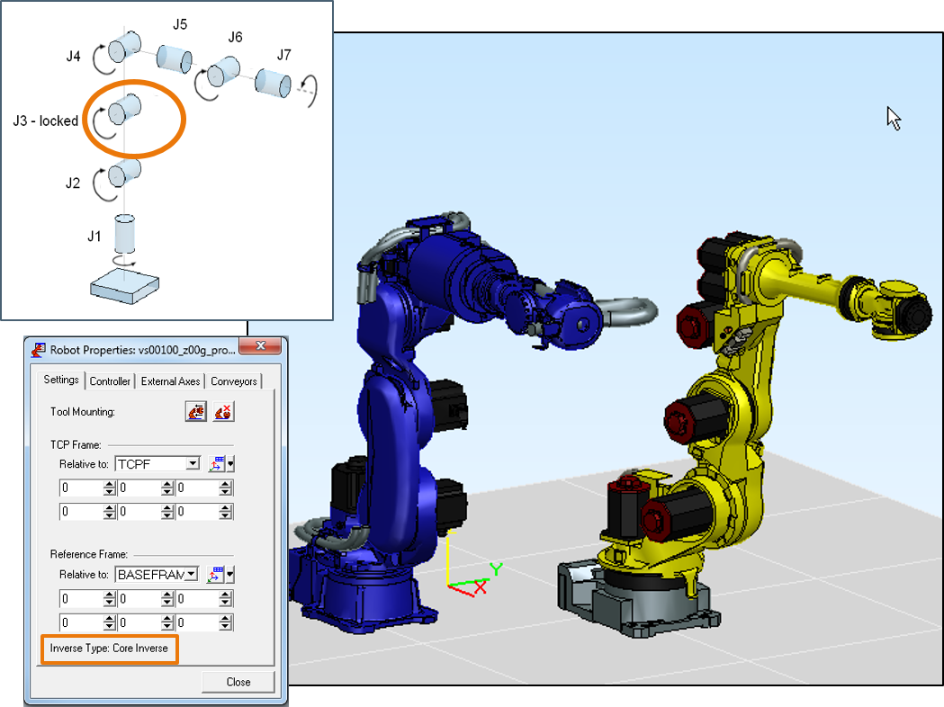
Inverse kinematics for seven degrees of freedom
An inverse algorithm was added to the core kinematics for support of a specific group of 7 degrees of freedom (DOF) robots. The supported robots are those in which the additional joint, J3 (locked), is parallel to joints J2 and J4.
Return to top. ^
PLCSIM Advanced connection
A new External Connection type was added to Process Simulate, namely, a direct API-based connection to PLCSIM Advanced. PLCSIM Advanced is a Siemens PLC emulator that allows for Virtual Commissioning using a software in the loop (SiL) solution. Together with Process Simulate this allows engineers to simulate both the robotic and PLC program execution at the same time on a single computer without any automation hardware. The PLCSIM Advanced connection supports multiple connections to both locally and remotely running PLC instances, two methods of Time Synchronization (SYNC and ASYNC mode) between Process Simulate and the PLC and the ability to exchange signals based on either matching addresses or signal names.
Return to top. ^
OPC Unified Architecture connection
The OPC Unified Architecture (UA) connection for hardware in the loop (HiL) solutions has now been enhanced to allow users to define an “Item Header” which acts as a prefix added to the signal name of any signals sent or read by Process Simulate from the OPC UA server. This allows users easier signal mapping by having shorter signal names in Process Simulate and adding a fixed prefix dynamically and automatically during simulation instead of manually. This is relevant for OPC UA servers such as Siemens SIMATIC Net and many others, and also matches the OPC UA client’s behavior in Process Simulate to that of its OPC DA client.
Return to top. ^
Line simulation performance
Many fixes related to Line Simulation (CEE) performance have been delivered. The fixes vary across many different applications, but you should experience significant improvement in simulation performance when running in Line Simulation mode. In addition, the new beta collision detector supports Line Simulation related objects such as Sensors and Conveyors, which will provide you with even better simulation performance thanks to better collision detection performance.
Return to top. ^
Human factors and ergonomics.
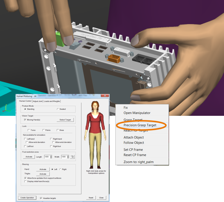
Fine pinch grasp
Precision grasping of small objects has been made easier with the new Precision Grasp Target option in the Human Posturing Dialog-Hand context menu. With this option, selected objects are automatically grasped using a precision pinch grip. As with the whole hand autograsp, the fingers are positioned using collision detection with the part. In addition, new context menus have been added to the hand Joint Manipulation panel with options to enable you to more speedily accomplish finger posturing for small object manipulation.
Return to top. ^
Finger and palm manipulation
You can now manipulate fingertips individually using inverse kinematics and locking. The system draws a box around the distal finger segment to indicate the locked state. Further, a context menu accessible from the palm area of the Hand Adjust dialog now allows you to manipulate the palm position directly from the dialog.
Return to top. ^
New anthropometric databases
New anthropometric databases have been added to this version providing a more accurate representation of North American populations. Specifically, a database for mid-western Mexico (Jalisco region) is now included, and updates from the 2011-2014 NHANES and the 2012 ANSUR II data are now available. More information about these databases are included in the documentation.
Return to top. ^
Task Simulation Builder (TSB) enhancements
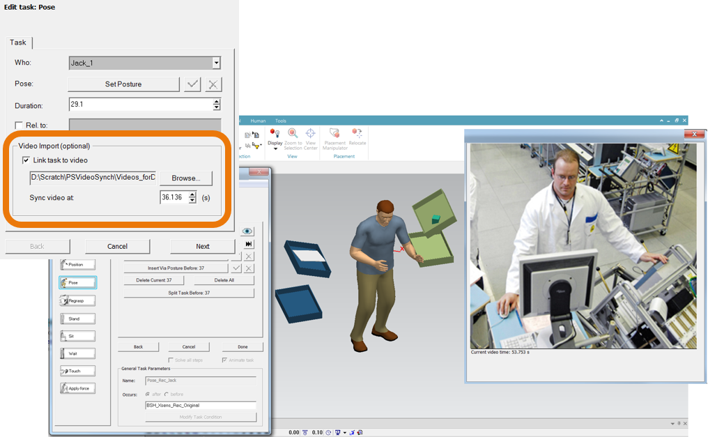
Video synchronization
Video recordings made during a motion capture session can provide important ergonomic information when evaluating the motions in the simulation environment. For example, if hand postures are not tracked, the video can provide information on precise timing for an object grasp. It is now possible to allow for exact simulation synchronization with recorded video. Synchronized, simultaneous viewing of recorded video with the associated simulation is made much easier and less error prone with this motion tracking video synchronization feature.
 Return to top. ^
Shuffle and side stepping
In this version, walk simulation capability has been enhanced to better simulate typical short displacement “shuffle” stepping. There is now better support for situations when a person would take only a few short steps to reposition or reorient themselves. Side steps, or step sequences are now automatically inserted for these situations. Addition of these single or “shuffle” step sequences can dramatically enhance the visual realism of the simulation.
Return to top. ^
Walk carry posture
When carrying an object, people typically adopt postures that do not interfere with their walking motion or vision. TSB attempts to automatically predict a neutral carry posture, but in some cases, particularly with larger objects, user definition of the carry posture can be beneficial. With this release, it is now possible for you to define details of the walk postures. The Change Walk Posture control allows users to define the posture for torso and arm(s) grasping objects, and maintains it throughout the Walk action. To allow complex upper body postures to be used in cramped environments, for example when ducking under something, the Go and Get tasks also allow an upper body posture to be defined and persisted, even when no object is carried. The system maintains motion realism using predictive walking and head/eye gaze behaviors to control the lower body (pelvis and legs) as well as the head. The ability to represent real-world carry and walk postures helps improve simulation realism and accuracy of ergonomic evaluations.
Return to top. ^
Motion tracking
The ability to use motion tracking data frames within the TSB Pose task provides a powerful way to incorporate complex movements in a simulation. This functionality has been further enhanced in this version, now with even more flexible ways of analyzing the captured data for ergonomic issues. You can now insert Apply Force tasks to accurately simulate task demands. Supporting this, objects can be created on-the-fly, scaled to size, and annotated with weight and force parameters. You can use Regrasp tasks to better control manipulation of untracked objects. A new “Ergonomics Properties” interface allows you to describe task details instantly during task creation. For those of you using the add-on EAWS ergonomic assessment tool, the ergonomic details are automatically incorporated into the analysis, significantly reducing the need for manual entry later.
Return to top. ^
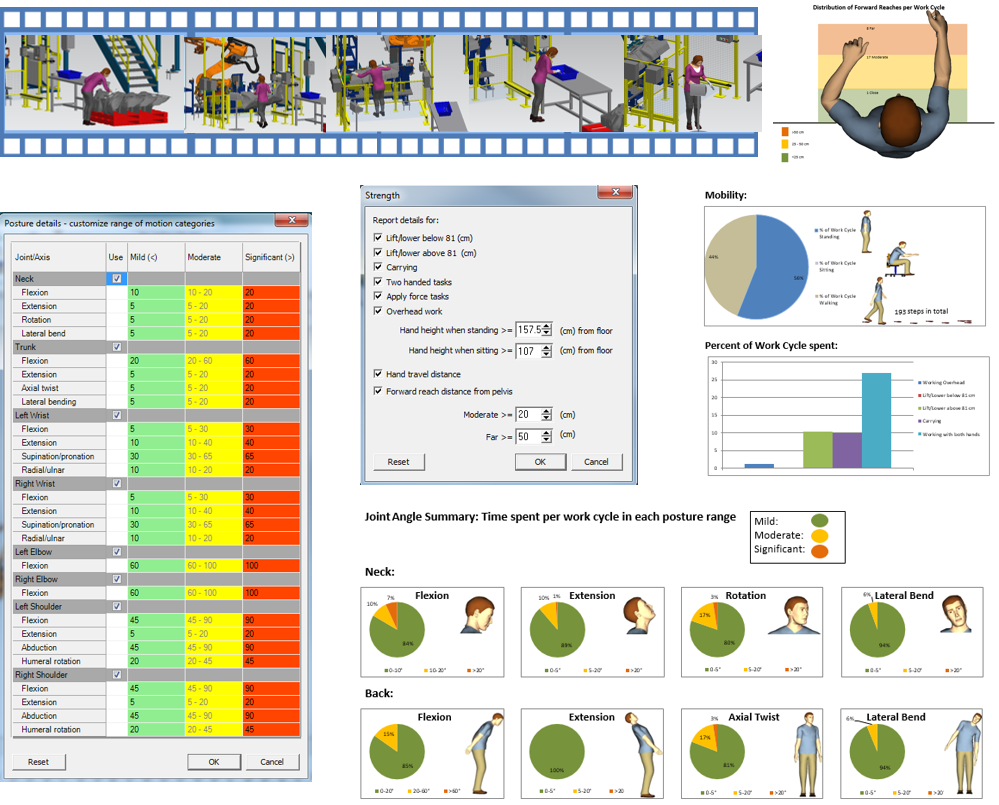
Physical demands report
A new ergonomic assessment tool has been added to the TSB system. A comprehensive assessment of postural and exertion demands for a task sequence can be useful for optimizing workplace layout configurations, for example, to help quickly get an overview of potential musculoskeletal risk factors, or to assess if a job might be suitable for a worker with specific restrictions. To help with this, Process Simulate Human now includes a Physical Demands Report that summarizes valuable postural and task demand information in an easily interpreted report.
Return to top. ^
NIOSH reports
The NIOSH lifting equation is a widely recognized tool for analysis of lifting jobs. While the tool was available in the product earlier, with this release, the NIOSH assessment is integrated within the TSB system, such that NIOSH lifting assessments can be automatically generated from a TSB simulation.
Return to top. ^
Walk analysis report
In an assembly workcell, walk actions can represent hidden costs including unproductive time, or increased chance of part damage due to collisions with surroundings. To help better analyze the walk requirements within a workcell, it is now possible to create a comprehensive analysis of the walk actions, accessible through the TSB reporting dialog. Specifically, the new TSB Walk Report provides a graphical “spaghetti diagram” of all the walk paths, and a tabular summary of the individual walk actions for each worker in the simulation, including duration and distances.
Return to top. ^
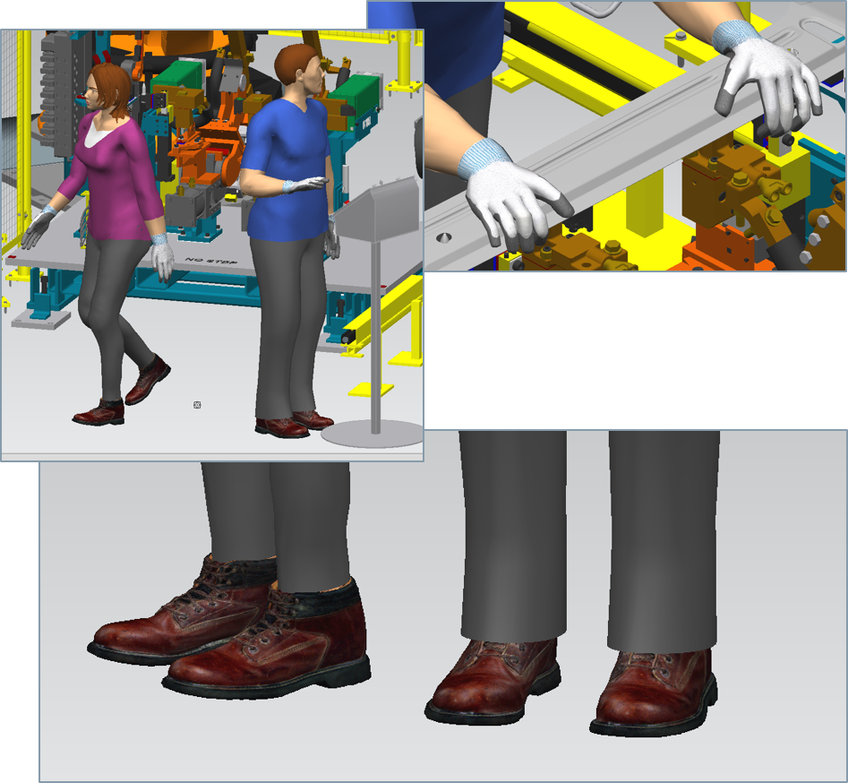
Scalable work boots and gloves
New figure variants with protective work boots and gloves have been added to the Human Library. Based on the existing v70 deformable skin figures, the new male and female figures feature scalable work boots and gloves. You can scale the height of the boot sole and the thickness of the gloves via the scaling dialog.
Return to top. ^
Motion capture system support
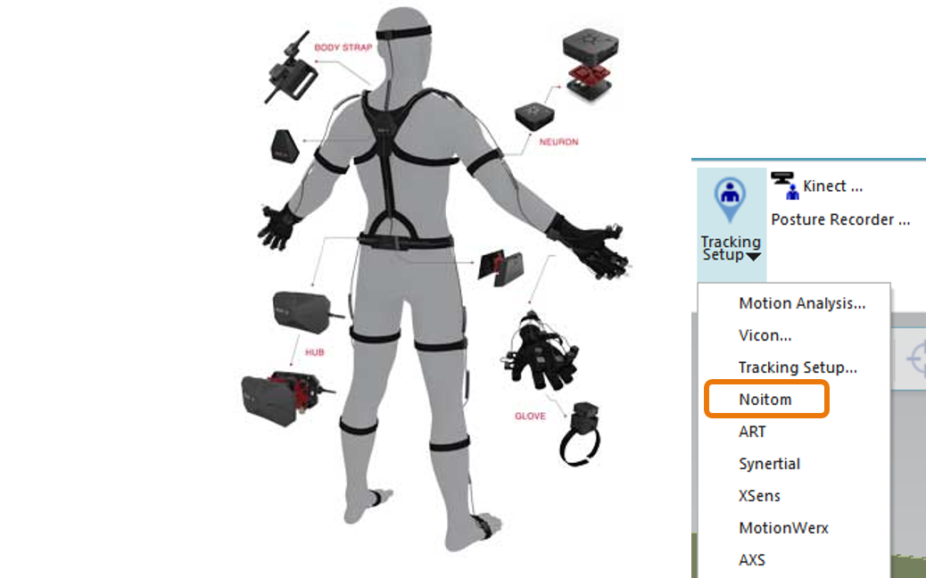
For those of you using the separately licensed Motion Capture Toolkit, a new hardware system has been added to the menu of supported devices. The Noitom Perception Neuron system is a low cost, gyro-based system that features both entire body and hand tracking capabilities. The drivers needed to communicate with this hardware are now available.
Return to top. ^
Posture library enhancements
To speed the posturing of the figure for analysis, it is often helpful to start with a posture close to the desired one. With this release, the posture library has been enhanced with eleven new postures that are relevant for typical seated and standing assessments. Using these new postures, only minimal adjustments may be needed to manipulate the figure into the desired configuration. For ease of use, the posture libraries for the hands and whole body have now been consolidated within the Human Posturing Dialog. This makes it easier to work with the pre-defined postures in concert with the other posturing capabilities of the dialog.
Return to top. ^
Human in Process Simulate Standalone on Teamcenter
Working on Human workflows in cooperation with other groups requires efficient data exchange between all parties. In some cases, however, not all groups have access to Teamcenter. Now, there is Human support for Process Simulate on Teamcenter Standalone, allowing Process Simulate Human simulation environments loaded from Teamcenter to be shared and modified by users without Teamcenter access. Studies can then be resynchronized back to Teamcenter at a later date.
Return to top. ^
Plant simulation and throughput optimization.
Active Workspace Client
Plant Simulation 14 provides an integrated Active Workspace (AWS) Client. This brings standardized Active Workspace/Teamcenter workflows directly to your simulation application.
Return to top. ^
PLCSIM Advanced connection
The new PLCSIM Advanced interface object connects Plant Simulation models with a PLC program running in a virtual PLCSIM Advanced PLC. PLC-Out signals are copied to Plant Simulation variables and simulation object attributes while Plant Simulation writes PLC-In signals that are sent to and used by the PLC program running in PLCSIM Advanced. Time synchronization between PLCSIM Advanced and Plant Simulation supports aligned time progress on both sides.
Return to top. ^
OPC Unified Architecture connection
Connecting Plant Simulation to PLC controls is now possible through the enhanced OPC Unified architecture (UA) Server/Client infrastructure, offered and developed through the OPC Foundation. Due to the OPC UA standardization you can connect Siemens PLC devices such as S7-1200, S7-1500, etc., any other PLC brand supporting OPC UA, and MES and shop floor software with an OPC UA interface. The OPC UA interface is independent from the Microsoft COM/DCOM protocol and is easier to configure/implement in a network. The OPC server can reside on IT components that are not running a Microsoft operating system, for instance, a Siemens PLC or PLCSIM Advanced.
Return to top. ^
Live 3D labels and charts
You can now show object names and labels in a 3D model view. Name and label positions and orientations are freely configurable. The caption setting for names is active by default for information flow objects such as methods, tables, etc. Position settings can be done on the caption tab of the 3D properties dialog.
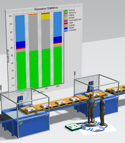
You can now visualize live charts and plots on graphical chart boards that are part of your 3D scene in Plant Simulation. Graphical chart boards can be scaled and positioned in the 3D scene similar to all other graphical objects.
Return to top. ^
Moveable unit (MU) stacking and animation area
Stacking for parts, containers and boxes is possible now. You can, for example, build piles of plates or boxes in a floor storage area. You can use the pick and place robot for part and container stacking without any additional configuration or coding. The robot automatically calculates pick and drop positions according to the boundaries of affected objects. The new animation area simplifies regular animation for parts in store objects or containers, and on vehicles. You can modify the animation area size, height and orientation. The parts are displayed on this area according to the objects capacity defined by its x-y-dimensions. With a single animation path marker you can additionally define the part orientation on the animation area.
Return to top. ^
Automatic scaling for movable objects
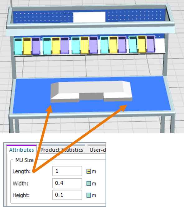
The new setting in the 3D properties dialog of movable objects enables auto-scaling of the geometry according to the object size. Auto-scaling is active by default for the object classes entity, container and transporter. With auto-scaling active you always get geometries that fit exactly to the object settings for length, width and height. Changes to the object size during a simulation run, for example as a result of a stamping or cutting process, are automatically displayed correctly.
Return to top. ^
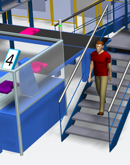
Operator using stairs and working on different levels
The walking operator can now use stairs to reach working areas on different height levels. With this feature you automatically get exact worker/operator timing for walking and movements on the shop floor. The Sankey diagram also now supports walk paths over stairs.
Return to top. ^
Sankey chart for operators on free walk paths
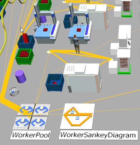
The new Worker Sankey Diagram shows worker and operator walking paths on the shop floor. The path thickness reflects the usage of each path section, giving an immediate overview on areas with high or low operator walk activities. You can use several Worker Sankey Diagram objects in a simulation model, observing different operator classes as regular workers, maintenance staff, etc.
Return to top. ^
Virtual reality.
Virtual reality
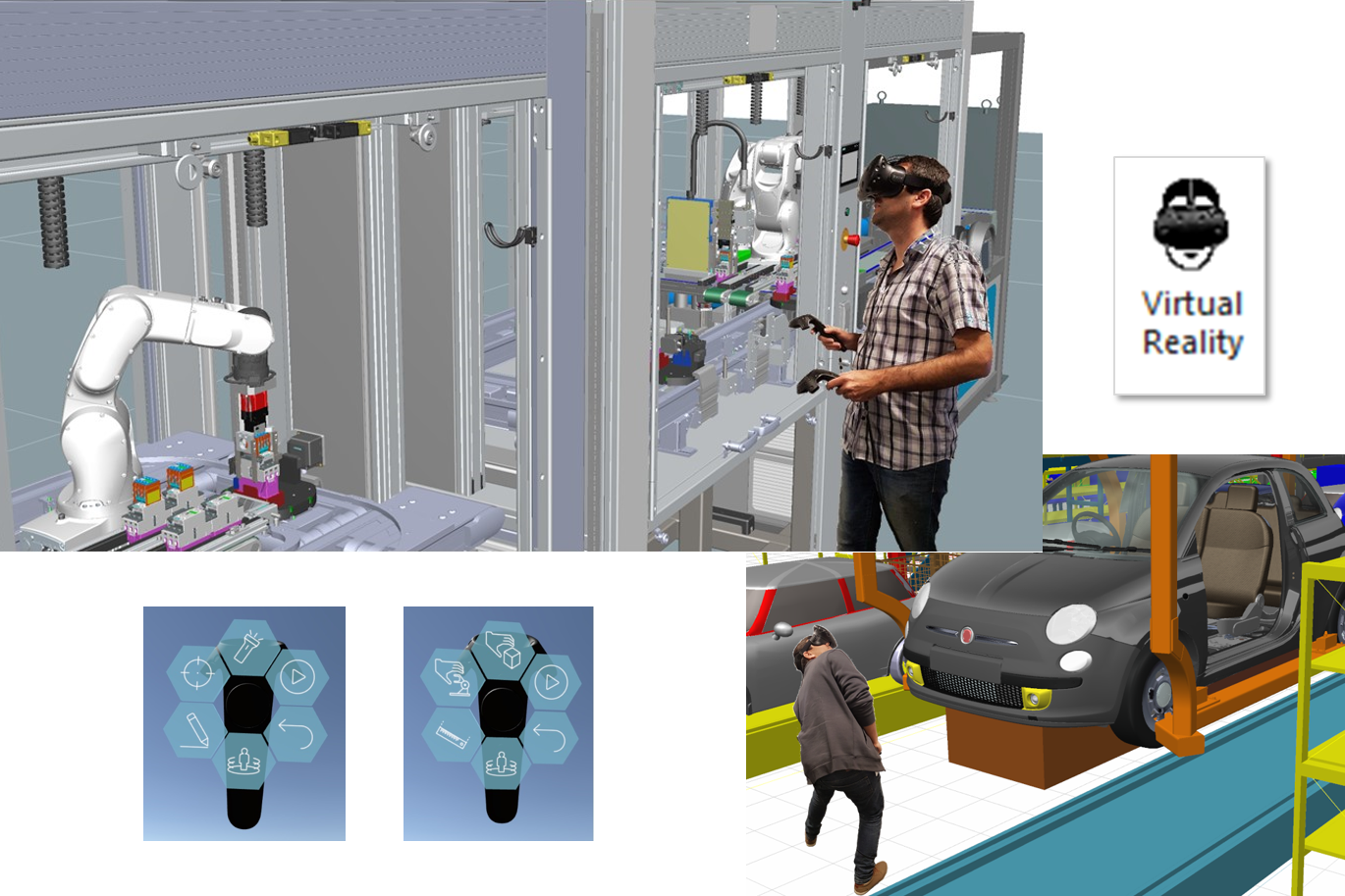
You can now load Process Simulate studies into a Virtual Reality (VR) world, using VR hardware, to immerse yourself in the manufacturing environment. This exciting new technology can increase the quality of the process as you identify issues and optimize manufacturing processes faster thanks to feeling as if you are right there in the scene. Process Simulate Virtual Reality is easy to use and enables interaction with other workers that is simple and intuitive. As the loaded data is connected to Process Simulate, changes in the VR environment automatically update the data in the study. Wearing the VR headset and using the hand-held controllers, you can teleport yourself around the space, highlight objects, measure, add markups, illuminate dark areas with a flashlight, play simulations and even move objects and jog robots. The VR window in Process Simulate lets users not wearing a VR headset watch a 2D monitor to see the same view as the person that is immersed, so that both of them can communicate and collaborate.
—–
> Watch this video to learn more.
—–
This release supports only the HTC Vive™ VR headset. For more details and specifications, please see the release notes.
Return to top. ^
General enhancements, usability improvements and IT updates.
Tecnomatix 14 offers several new enhancements, usability improvements and IT updates to make Tecnomatix solutions more capable, enjoyable to use and easier to manage.
General enhancements
Process Simulate Standalone on Teamcenter
Process Simulate Standalone now enables more complete workflow for time-based studies such as those including weld spot and continuous MFG operations. Users with limited access to a Teamcenter server, such as tier 2 suppliers, can now work with offline study files, for extending the process and plant structures, enriching them with new continuous operations, performing robotic path planning and simulation, and even for modifying the geometric and kinematic aspects of components when needed. If more Teamcenter objects are required in the offline studies, you can open them in Process Simulate while connected to the relevant Teamcenter server and use different commands to retrieve Teamcenter data as additional parts, MFGs, and resources into the offline study. Human simulation is also supported for ergonomic workflows. Process Simulate on Teamcenter connected users, such as OEMs, can receive the offline time-based study data from a Process Simulate on Teamcenter Standalone machine, where the data was edited, and open it in Process Simulate on Teamcenter while connected to update it back to the Teamcenter server.
Return to top. ^
Process Simulate and/or RobotExpert
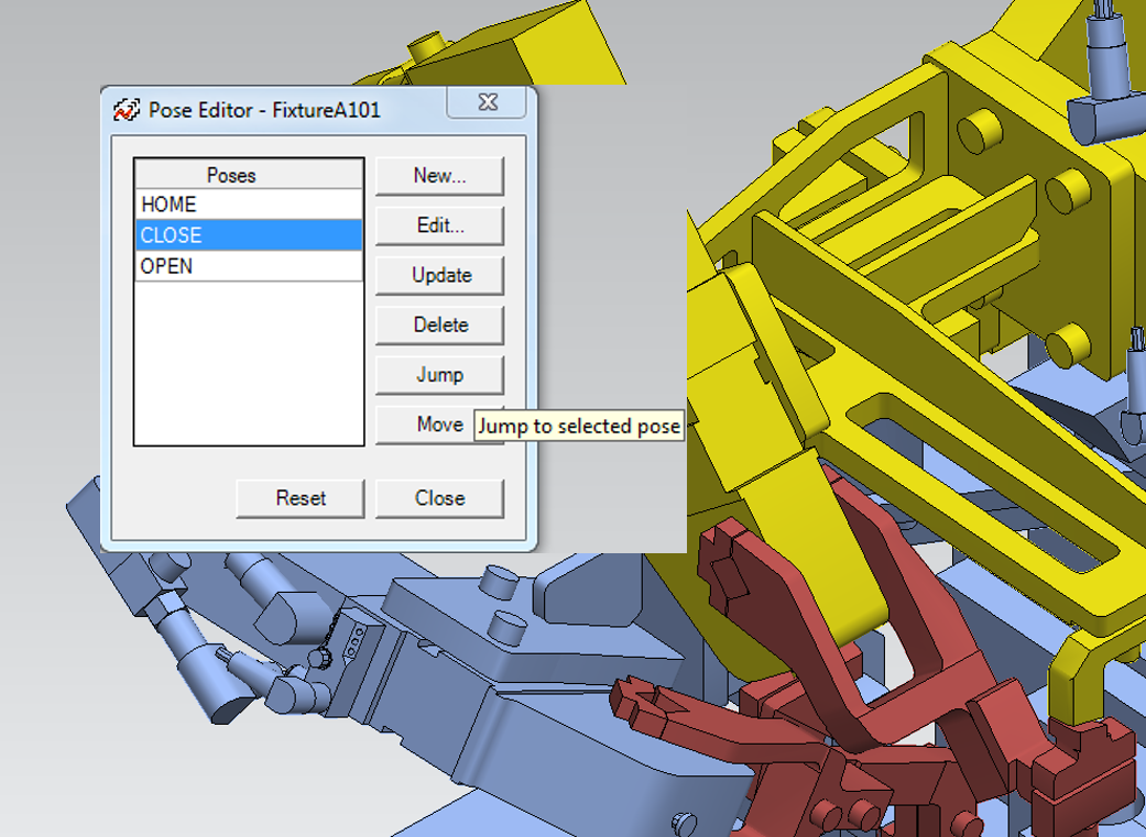
Move to pose
The move button was added to the pose editor dialog to move the selected device or robot in a simulation to the selected pose. This makes it easier to detect if there are any collisions on the way to the selected pose from the device or robot’s current position.
Return to top. ^
Gun cloud
The new gun cloud command lets you create a gun cloud that simultaneously displays a weld gun at every weld location in a weld operation. This is also possible for operations with multiple guns. The dialog box enables export of studies with a gun cloud as a JT for fixture planning. The gun cloud command allows you to export and share guns on locations with tool designers, with control over what to include in the exported JT (all visible data, only assigned parts and guns, etc.). This command also works for continuous and generic robotic operations.
Return to top. ^
Simulation playback speed
The simulation time Interval dialog box now contains an enhanced slider to set the speed of the simulation from the fastest to slowest speed with actual speed (1:1) in the center. The slider even allows you to reduce the simulation speed to a level slower than the actual speed.
Return to top. ^
Modeling Save-as
You now can save an existing component as a new prototype, with a new instance. The system sets the modeling scope to the new instance and modifications that you make to the instance are not propagated to any instances of the original source prototype. This capability is available for Process Simulate on eMServer.
Return to top. ^
Object tree folders
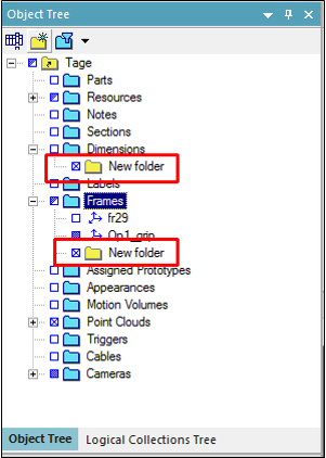
You can now create folders in the object tree to help organize similar objects in relevant folders.
Return to top. ^
Cables
You now have additional functionality for working with cables, also enabled in Process Simulate on Teamcenter. New functions include define fulcrum length, define twist angle, and allow damping of cable oscillations during simulation. The cables API provides additional capability for extracting cable parameters.
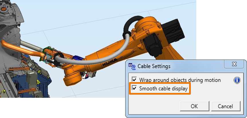
A new cable settings dialog is now available. The wrap around objects option determines whether cables wrap around visible parts and resources during robot motion. When cleared, it is possible the cable will penetrate objects. Clearing this option improves the performance of cable simulation. Users can now improve the appearance of cables with the new smooth cable display option. This causes cables to display as natural, smooth curves.
Return to top. ^
Automatic path planner
You now can impose low and high limits on any of the axes of translation to improve path planning results for object flow operations in the Automatic Path Planner (APP). After setting low and high limits, the limits are directly shown in the graphics view. During path planning, APP limits the motion to stay within the defined translation limits so users are able to easily constraint the APP algorithm in order to get better results.
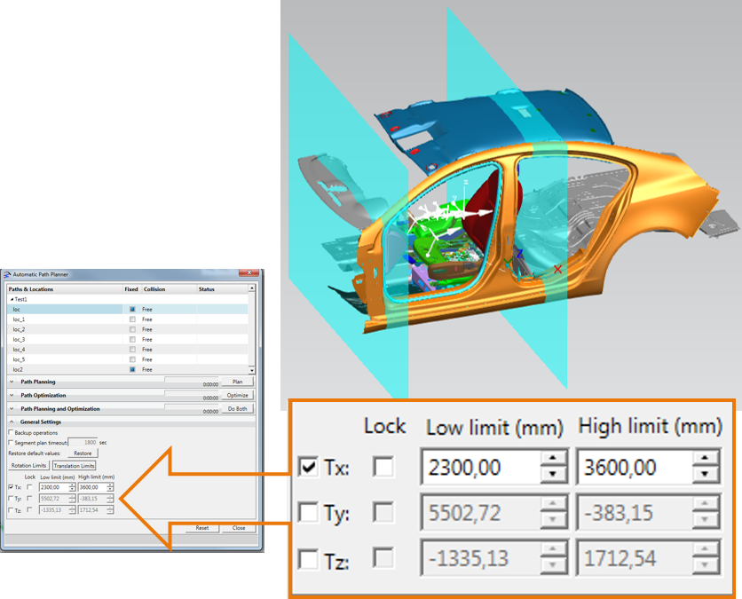
You can also impose low and high limits on any of the axes of rotation to improve path planner results for object flow operations. After setting low and high limits, the preview button simulates the permitted rotation. APP automatically computes collision-free operations when the start and end locations are collision-free and it now better manages contact and minor collisions of the input locations in order to create realistic collision-free paths.
Additionally, there is a new capability in assembly scenarios for object flow operations to constrain the APP calculation geometrically in one, two or three axes. This enables you to guide the APP solution search to arrive at the most optimal solution for your needs by configuring the translation and/or rotation limits for the simulated part at all the fixed locations in the operation.
Return to top. ^
Continuous process
The mirror command now also creates the mirror inversion of an existing continuous operation including, continuous operations, seam operations, MFGs (curves), locations, and resources. This simplifies the planning of continuous processes that need to be repeated with mirror inversion.
Changing the torch alignment spin angle to allow reachability to arc locations leaves the work and travel angles unchanged.
The paint create mesh status now gives a clear notification whether parts have XTBREP exact geometry, whether there is a previously created mesh, and if the mesh was created successfully.
The coverage pattern projection in the continuous process generator is now enhanced to better control the location orientation, as follows:
-
- Tangent – the location is tangent to the stroke whereby the movement vector is aligned with the stroke direction
-
- Tangent ZigZag – the location is tangent to the stroke, but maintains a unidirectional movement vector
Return to top. ^
Fast collision detection
The new beta collision detector can be activated in the Tecnomatix Doctor application. It now supports additional functionality in Process Simulate for checking collisions with wireframe entities and the ability to ignore them, the calculation of collision depth and the ability to fix collisions using the jump command, and support of the smart disassembly command in Process Simulate on Teamcenter.
Return to top. ^
Movie Recorder
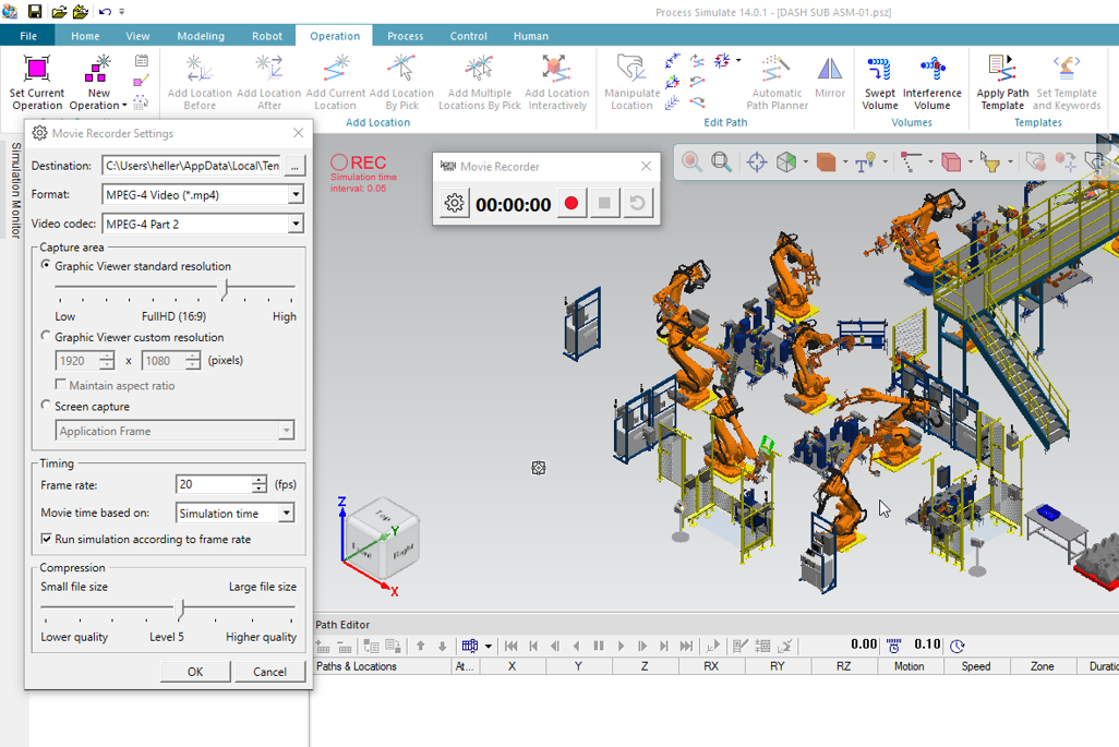
The new movie recorder gives you powerful and very flexible options to capture simulations or anything displayed on one or more of your displays. Launching the command displays a recording bar with icons for record, pause, stop and reset. After pressing the record button, the command displays a 3-second countdown timer before recording begins. Even after launching the countdown, you can easily delay the recording by hovering over the timer digit display, and the countdown resumes after you move the mouse away. According to your selection in the movie recorder settings dialog, simulations are recorded in real time or simulation time, in which case, the recorder takes the simulation speed setting configured in the sequence editor or path editor simulation settings dialog. The movie recorder settings also allow you to choose from a variety of video formats, to select either the graphic viewer or display content as the capture area, as well as the type of movie timing and the level of compression.
Return to top. ^
Usability improvements
Graphics viewer
The default graphic viewer background and light settings have been modified to unify the look with other leading Siemens PLM applications:
-
- The window background now uses the same gray color as NX and Teamcenter Visualization
-
- The intensity of light sources and their directions were modified to cause less reflection in the scene and to improve the visualization quality
You can customize the light intensities and background color using the options dialog.
Return to top. ^
Mouse button functionality
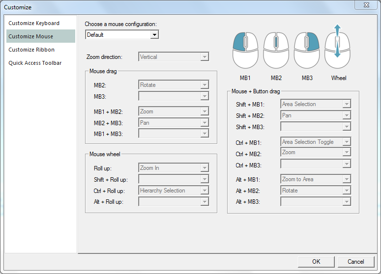
The default graphic viewer configurations of the mouse’s left, right and wheel buttons have been standardized to the settings used in NX for zooming, panning and rotating the view. You have the option to revert the mouse functionality to the previous, “legacy” behavior, or alternatively, to customize each button.
Return to top. ^
Pick and selection preview
With the elements of advanced user experience introduced in this version, hovering with the mouse from one object to another in the graphic viewer highlights each subsequent object with a selection preview color as the previous object returns to its non-highlighted color. In addition, while hovering on an object, the system displays a new preview marker on the object, according to the designated pick level and intent. When you click to actually select the object, the highlight preview selection color changes to the highlight selection color, and the pick intent selection marker icon changes to the selection icon. You can modify the highlight preview selection color and highlight selection color in the appearance tab of the options dialog.
Return to top. ^
Graphics viewer toolbar and search bar
The new graphic viewer toolbar helps you significantly reduce the frequency of mouse movements and diminish the need for switching between ribbon tabs. The toolbar is visible in the active graphic viewer and appears by default in the upper center of the window. You can drag it anywhere within the boundaries of the pane. The toolbar contains view-changing commands such as zoom, view center, etc., as well as pick level, measurements, dimensions and other commands that manipulate objects in the graphic viewer, including the placement manipulator.
The search command, which was located on the home ribbon, has been moved to the top right corner of the application. This provides you with more convenient, easily accessible search functionality. As you begin to type a word the search results start to display.
Return to top. ^
Location display
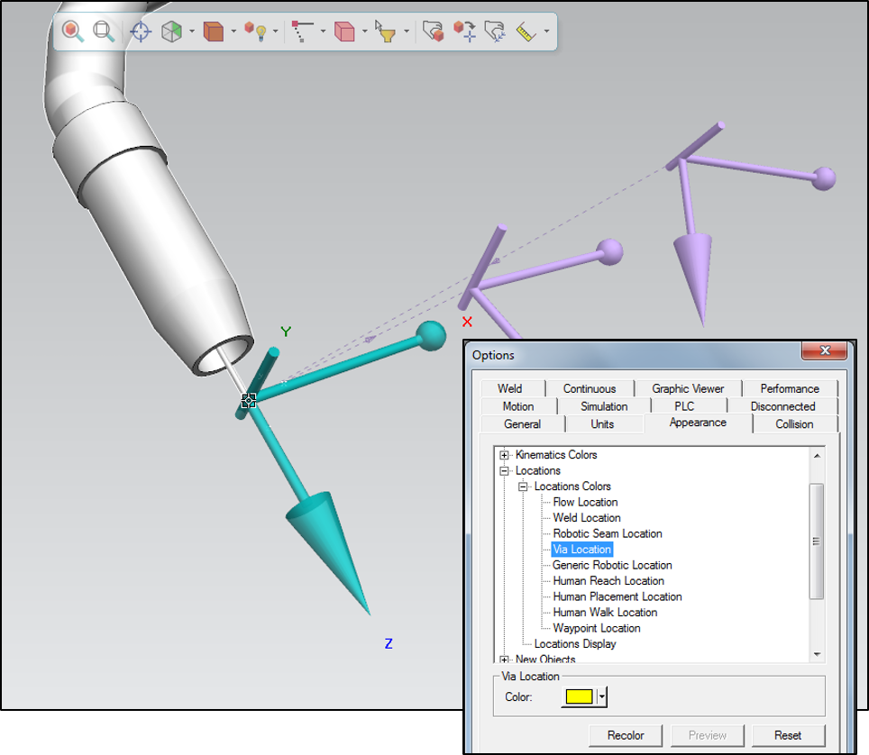
The representation of locations has been enhanced with the display of a pointing cone on the Z axis and a sphere on the X axis. From the appearance tab in the options dialog, you have options to change on which axis to place the cone, to keep the location axis size fixed or resizable when panning in or out, and to set a minimal size for the axis when zooming out. When selecting a single location the XYZ tooltip is displayed with the same colors as the working frame.
Return to top. ^
Welcome page
The welcome page displays upon opening the application and you can reopen it from the home tab on the ribbon menu. The welcome page now conveniently offers the option to select between standard and line simulation modes. A new splitter divides the recent files pane from the section displaying the new features. This allows you to expand or contract the area that contains the list of recently used files with their selected favorites. In addition, you can now change the system root from the welcome page, and can customize the page’s HTML format. Another convenient new capability on the welcome page is that you can right-click to remove study files from the recent files list.
Return to top. ^
Navigation cube
Tecnomatix applications display the 3D navigation cube in the graphic viewer. The cube’s clickable six faces: Front, Back, Right, Left, Top and Bottom offer you an easy way to change the view point. You can also change the view point by clicking the beveled edges at the intersection of every two faces and at the corners of every three faces, providing even more versatility in selecting a specific view. Clicking the Home button rotates the navigation cube to the view point corresponding to the top-front-right corner of the cube. You can click one of the two curved rotation arrows to turn the current view by 90 degrees in the direction of the arrow. Holding down the mouse button turns the view smoothly and continuously in the direction of the arrow. By clicking the settings icon, you can open the settings dialog with options to show/hide the navigation cube and/or its axes frame.
The look and feel of how the scene moves to the new view point is determined by the rotation method selected in the options dialog according to the Tecnomatix or Teamcenter Visualization method.
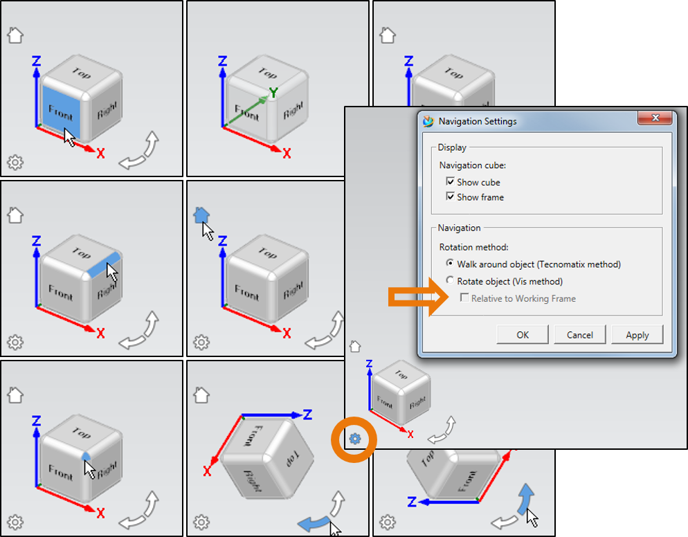
The animated viewing option in the graphic viewer tab causes a ‘fly to’ effect when rotating the view. The rotation method options were removed from the graphic viewer tab in the options dialog box and are now located in the navigation settings dialog box of the navigation cube. Activating the relative to working frame check box orients the cube to the working frame, for instance, pressing the TOP view will rotate the view to the TOP orientation of the working frame and not the world frame. When the navigation cube is hidden, the orientation frame is aligned to the working frame. The graphic viewer tab now contains the navigation settings button which also opens this dialog box.
Return to top. ^
Ribbon menu
You can customize default ribbon tabs by dragging additional commands or removing existing commands in the customize dialog. Pressing reset reverts tabs to their original configuration.
Return to top. ^
Object toolbar
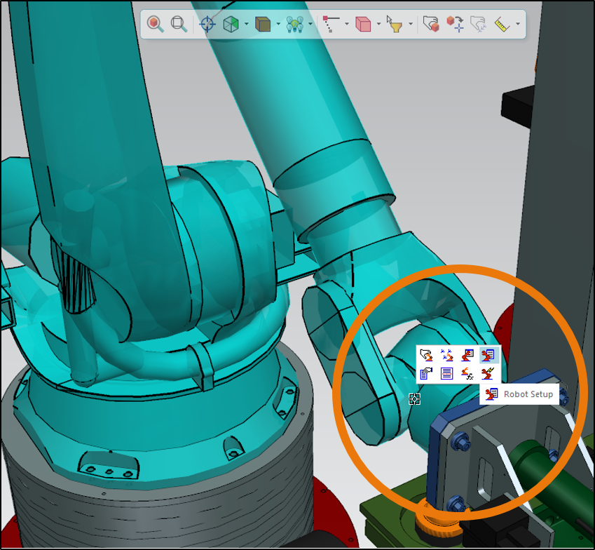
When you select an object the system displays a toolbar that contains the commands that are relevant to that object. This helps to minimize mouse travel, head, and eye motion when searching the ribbon for commands commonly used for the object. Moving the mouse away causes the toolbar to fade, and moving it further away causes it to disappear until selecting the object again. The content of the toolbar is contextual, and the toolbar changes for different types of objects. The object toolbar is displayed by default. You can hide it using the options dialog.
Return to top. ^
IT Updates
Tecnomatix 14 delivers the following IT updates and capabilities:
-
- CAD certifications for JT 10.2, NX 11 and CATIA V5-6R2016.
-
- The web-based BOP manager now supports Apache Tomcat 8.0.37, whereby the BOP manager is installed into an existing Tomcat installation.
-
- Improved search and replace commands and import/export functions have been added to Process Designer.
Return to top. ^
For complete details on the new features of Tecnomatix 14, please refer to the release notes and new features presentations offered for the individual products.
Return to top. ^
Of course, with any new software version there are many exciting new features to talk about and Tecnomatix 14 is no exception. We have worked hard to compile all of the great new features of the Tecnomatix 14 release for you here.
Yours in digitalization,
![]()
(on behalf of the entire Manufacturing Engineering Software product team)


![Automation World features Tecnomatix Process Simulate: the essential software for virtual commissioning [ARTICLE]](https://blogs.stage.sw.siemens.com/wp-content/uploads/sites/7/2024/03/automation-world-process-simulate-2-395x222.png)
Comments