Take scan test out of the critical path
By Ron Press, Mentor Graphics
DFT with less risk to your design flow? Here’s how.
Integrated circuit complexity and integration continuously advances, posing challenges to the development process. Market profitability, however, demands that products be designed and produced as fast as possible. DFT (design for test) tools are used to make the designs more easily tested and to produce production test patterns. Traditionally, much of the DFT work that changes the design occurred late in the design cycle and pattern generation was in the critical path of design completion. In recent years, DFT and pattern generation is undergoing a shift to occur earlier in the design development flow.
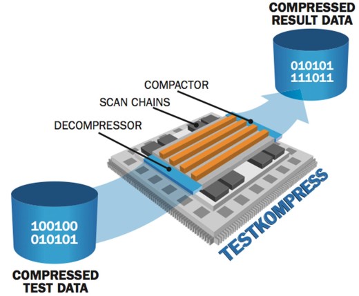
Logic is tested by configuring sequential elements in the design into many shift registers called scan chains that a tester then loads and unloads. This lets ATPG (automatic test pattern generation) efficiently and automatically test any type of design. But, as designs kept growing in size, the test time and data increases as well. As a result, about fifteen years ago embedded compression logic was added to the scan chain interface, which provided 100× reduction in test time and data [F. Poehl et al, ITC, 2003. 10.1109/TEST.2003.1271110]. The general setup of scan compression is shown in Figure 1.
Figure 1 Embedded test compression is now a standard methodology for testing ICs.
Traditionally, compression logic was often added after the gate-level design was complete, so designers would know exactly how many scan chains exist. So the first “shift left” of DFT is to create embedded compression logic at the RTL (register transfer level) design or earlier, as illustrated in Figure 2.
Figure 2 Compression insertion can be moved before RTL, making it independent of synthesis.
With recent features in embedded compression, you can estimate the maximum range of internal scan chains used for embedded compression and then slightly over-specify them. Then, the RTL for embedded compression can be completed early in the design flow, even before design RTL is ready. If some of the scan chains or scan channels aren’t used, the compression and pattern-generation tool can still work effectively. This provides flexibility to handle additional scan chains that occur late in the design process due to ECOs or if chains are added for test points such as EDT Test Points. The test compression logic is also flexible enough to use different numbers of input channels, which could change due to packaging or due to tester limitations.
Another important industry problem is how to deal with growing design sizes. With RTL embedded compression insertion, the DFT work is done earlier but the pattern generation still needs the gate-level design. As designs keep growing, it isn’t uncommon for designs of 40 million gates to require a week for pattern generation and we are now seeing designs in excess of 500 million gates.
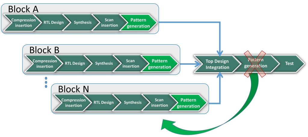
What most of the industry has done for these designs is another shift left; instead of waiting for the complete top-level IC design to be implemented before pattern generation—which puts it in the critical path—pattern generation is moved to individual blocks as they are ready, as illustrated in Figure 3. This way pattern generation is on a much smaller portion of the design so it is faster and requires a smaller workstation. But more important for many is that it can be completed much earlier in the design flow. Completion of DFT and pattern generation at the block level is referred to as hierarchical DFT. It is a plug and play approach which shifts the pattern generation out of the critical path.
Figure 3 Move pattern generation to the block level for large designs.
Moving the DFT insertion and pattern generation earlier in the flow takes DFT out of the critical development paths. Thus, working out DFT and test coverage issues can be done at a more practical time. In addition, when compression logic (and BIST) is inserted at the RTL then it is independent of the synthesis tool providing even more flexibility.
Liked this article? Then try this –
White Paper: A Guide to Power-Aware Memory Repair
This article was originally published on www.edn.com


